Endoscope system with scanning function

a scanning function and endoscope technology, applied in the field of endoscope systems, can solve the problems of image quality degradation, image brightness and/or dark parts of objects,

Active Publication Date: 2010-05-20
HOYA CORP
View PDF32 Cites 39 Cited by
  • Summary
  • Abstract
  • Description
  • Claims
  • Application Information

AI Technical Summary

Benefits of technology

[0007]An object of the present invention is to provide an endoscope system that is capable of adjusting the brightness of an observed image without image processing.

Problems solved by technology

However, if the depth from the scope tip portion to an observation area is not uniform, a part of the object image may become extremely bright and / or dark.
On the other hand, when carrying out image processing for correcting the brightness of an observed image, image quality degrades.

Method used


Image

  • Endoscope system with scanning function
  • Endoscope system with scanning function
  • Endoscope system with scanning function

Examples


first embodiment

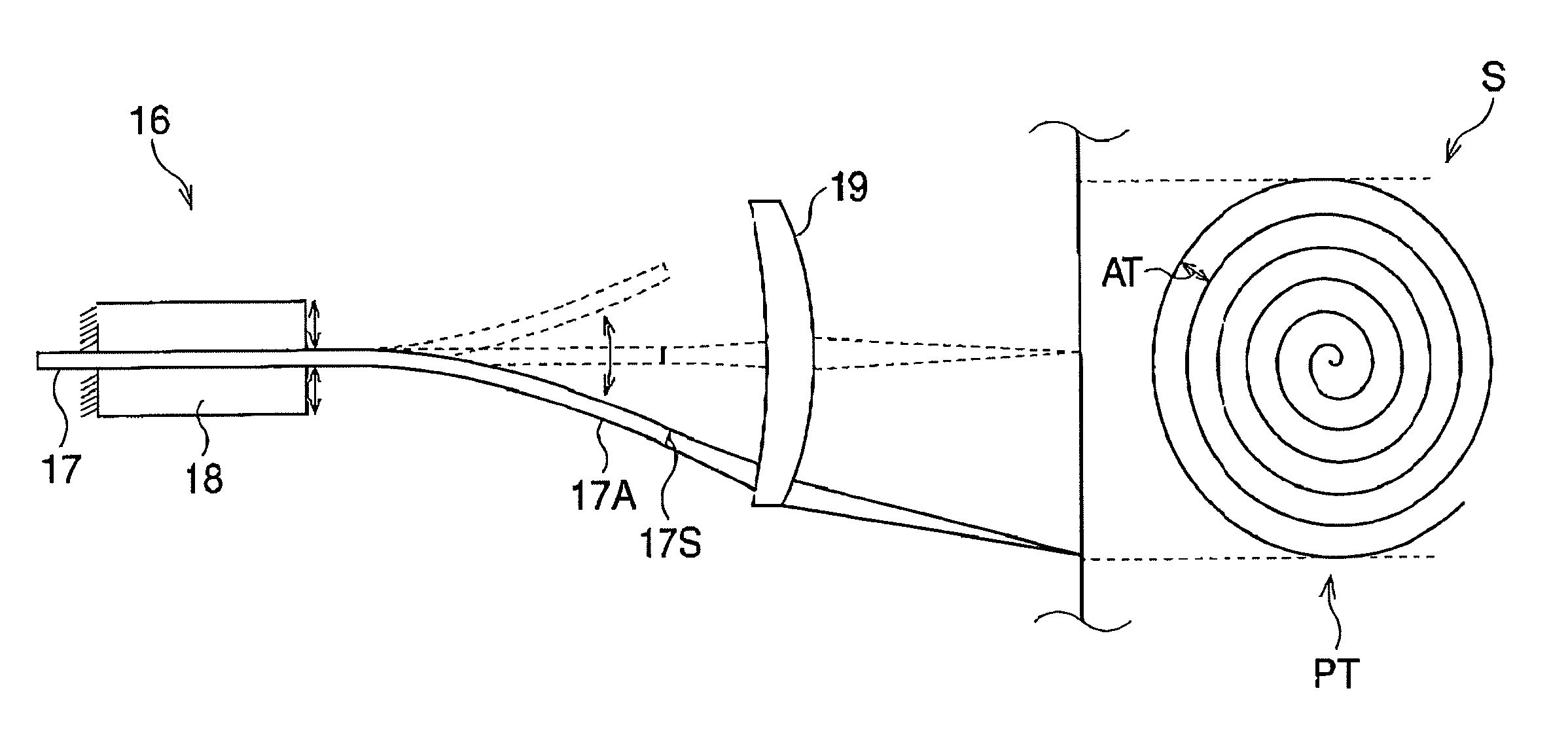
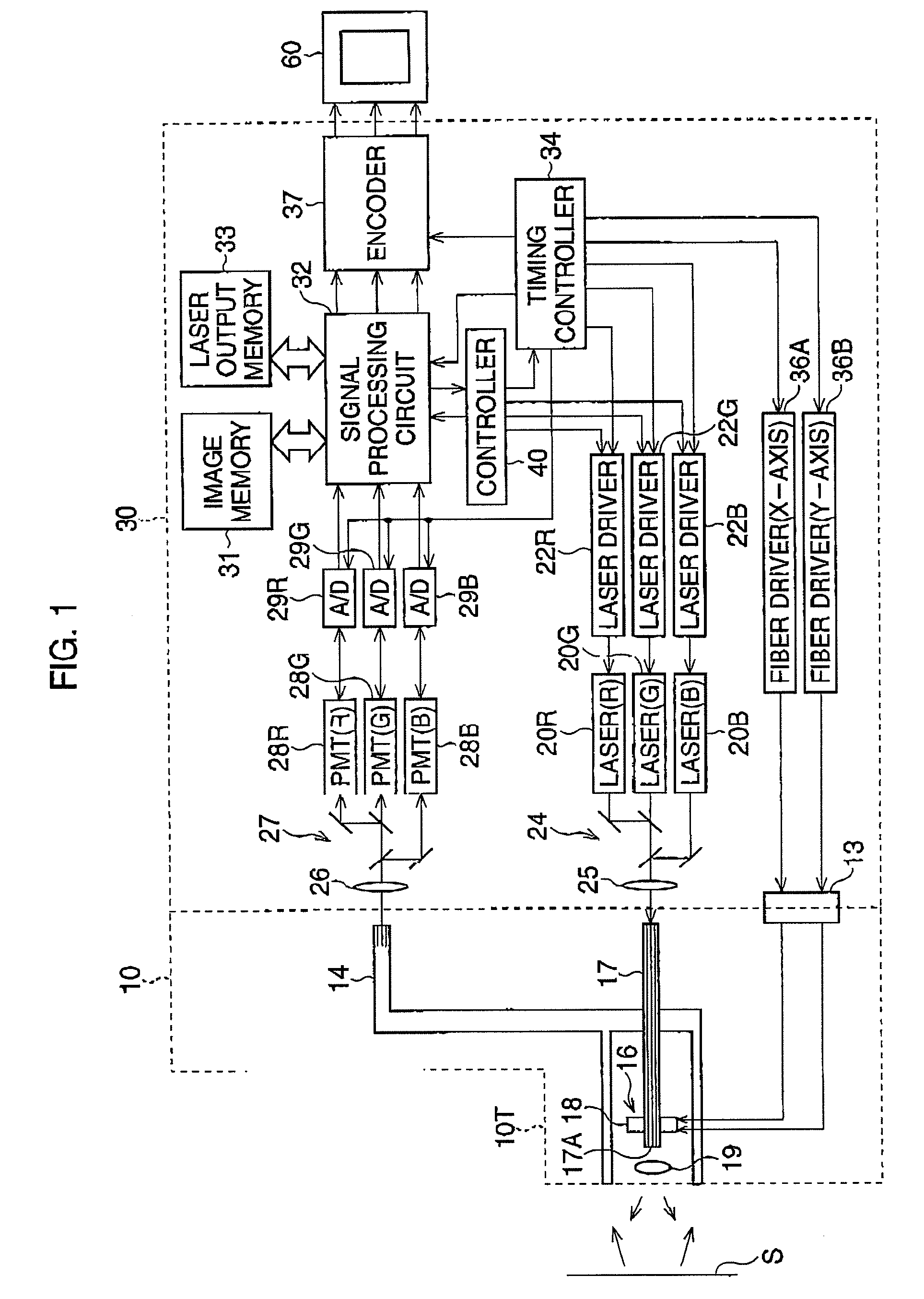
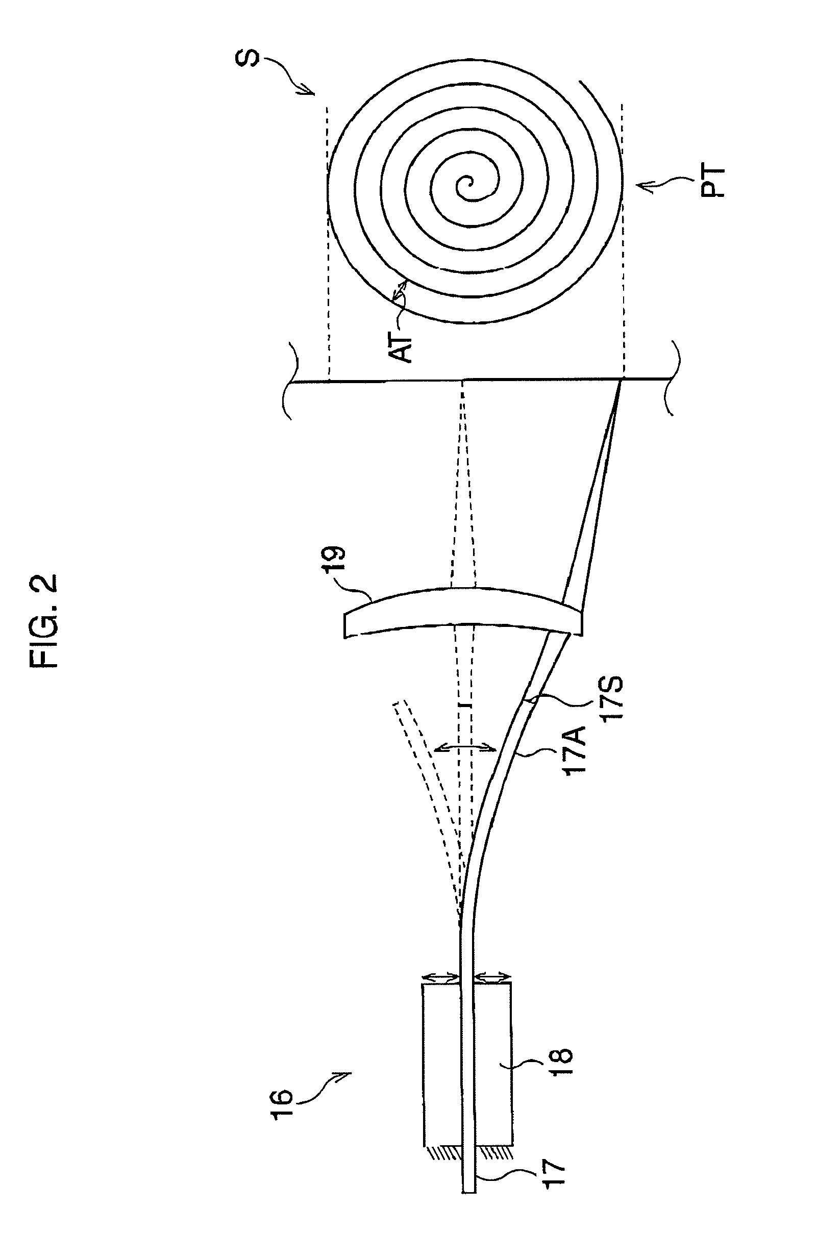
[0030]FIG. 1 is a block diagram of an endoscope system according to a FIG. 2 is an illustration of the scanning optical fiber, scanning unit, and spiral scan pattern.

[0031]The endoscope system is equipped with a processor 30 and an endoscope 10 that includes a scanning fiber 17 and an image fiber 14. The single mode type of scanning fiber 17 transmits illumination light, whereas the image fiber 14 transmits light that is reflected off an observation target S such as tissue. The endoscope 10 is detachably connected to the processor 30, and the monitor 60 is connected to the processor 30.

[0032]The processor 30 has three lasers 20R, 20G, and 20B, which omit red, green, and blue light, respectively. The lasers 20R, 20G, and 20B are driven by three laser drivers 22R, 22G, and 22B, respectively. The simultaneously emitted red, green, and blue light is collected by half-mirror sets 24 and a collection lens 25. Consequently, white light enters into the scanning fiber 17 and travels to the ...

second embodiment

[0073]FIG. 8 is a timing chart of a luminance level and an amount of illumination light according to the Luminance data shown in FIG. 8 include an edge portion E that corresponds to a boundary between a dark portion P and a bright portion Q. The dark portion P exists in a central portion of an observed image, whereas the bright portion Q exists in the surrounding portion. In this case, the laser output levels of the lasers 20R, 20G, and 20B are controlled such that the edge portion E is emphasized in a subsequent frame interval. Concretely, a laser output level is controlled so as to cause a difference to occur substantially before and after an edge portion E as shown in an arrow ZZ. Thus, a difference between a high luminance level P′ and a low luminance level Q′ adjacent to the edge portion E is enlarged and the contours of an object image are clearly displayed.

[0074]In the first and second embodiments, the brightness adjustment process is carried out in each frame interval. Howe...


PUM


Abstract

An endoscope system has a light source system configured to emit illumination light on a target area, a scanner configured to periodically scan the illumination light over a target area at predetermined time intervals, and an imager configured to receive the illumination light reflected from the target area and to acquire in succession a sequence of image-pixel signals. Further, the endoscope system has a luminance detector that detects in succession a sequence of luminance data of the object image from the sequence of image-pixel signals; and a brightness adjuster that adjusts the brightness of an observed image on the basis of the sequence of luminance data. Then, the brightness adjuster adjusts an amount of illumination light in accordance with a scanning position of the illumination light.

Description

BACKGROUND OF THE INVENTION[0001]1. Field of the Invention[0002]The present invention relates to an endoscope system that scans illumination light over a target to be observed, such as tissue. In particular, it relates to adjusting the brightness of an observed image.[0003]2. Description of the Related Art[0004]An endoscope system with scanning functionality is equipped with a scanning fiber such as a single mode type fiber, which is provided in an endoscope. As described in Seibel et al. (U.S. Pat. No. 6,294,775), the tip portion of the scanning fiber is held by an actuator such as a piezoelectric device, which vibrates the tip portion spirally by modulating and amplifying the fiber's vibration. Consequently, illumination light passing trough the scanning fiber is spirally scanned over an observation area.[0005]Light reflected off the observation area is entered into an image fiber, and is transmitted to a processor via the image fiber. The transmitted light is transformed to image...

Claims


Application Information

Patent Timeline
Patent Type & Authority Applications(United States)
IPC IPC(8): H04N7/18
CPCA61B1/00009A61B1/00172A61B1/043A61B1/0638A61B5/0062A61B1/063G02B23/2469G02B26/103H04N5/2256H04N5/2354H04N2005/2255A61B5/0084A61B1/0655H04N23/555H04N23/56H04N23/74
Inventor SHIBASAKI, YUICHI
Owner HOYA CORP
Why Eureka
Try Eureka