Illuminative apparatus

Inactive Publication Date: 2008-07-10
OMNILUX LIGHTING
View PDF14 Cites 31 Cited by
  • Summary
  • Abstract
  • Description
  • Claims
  • Application Information

AI Technical Summary

Benefits of technology

[0007]An advantage of the light array of the present invention is the adjustability of the luminance of the light emitted from it.
[0008]Another advantage of the light array of the present invention is a simple structure and therefore

Problems solved by technology

Problems have been encountered the assembly and use of this conventional light array.
Firstly, it is troublesome to assemble all these elements.
Therefore, it requires a lot of energy in maintenance.
Secondly, the structure of each light is complicated.
Therefore, the c

Method used


Image

  • Illuminative apparatus
  • Illuminative apparatus
  • Illuminative apparatus

Examples


Example

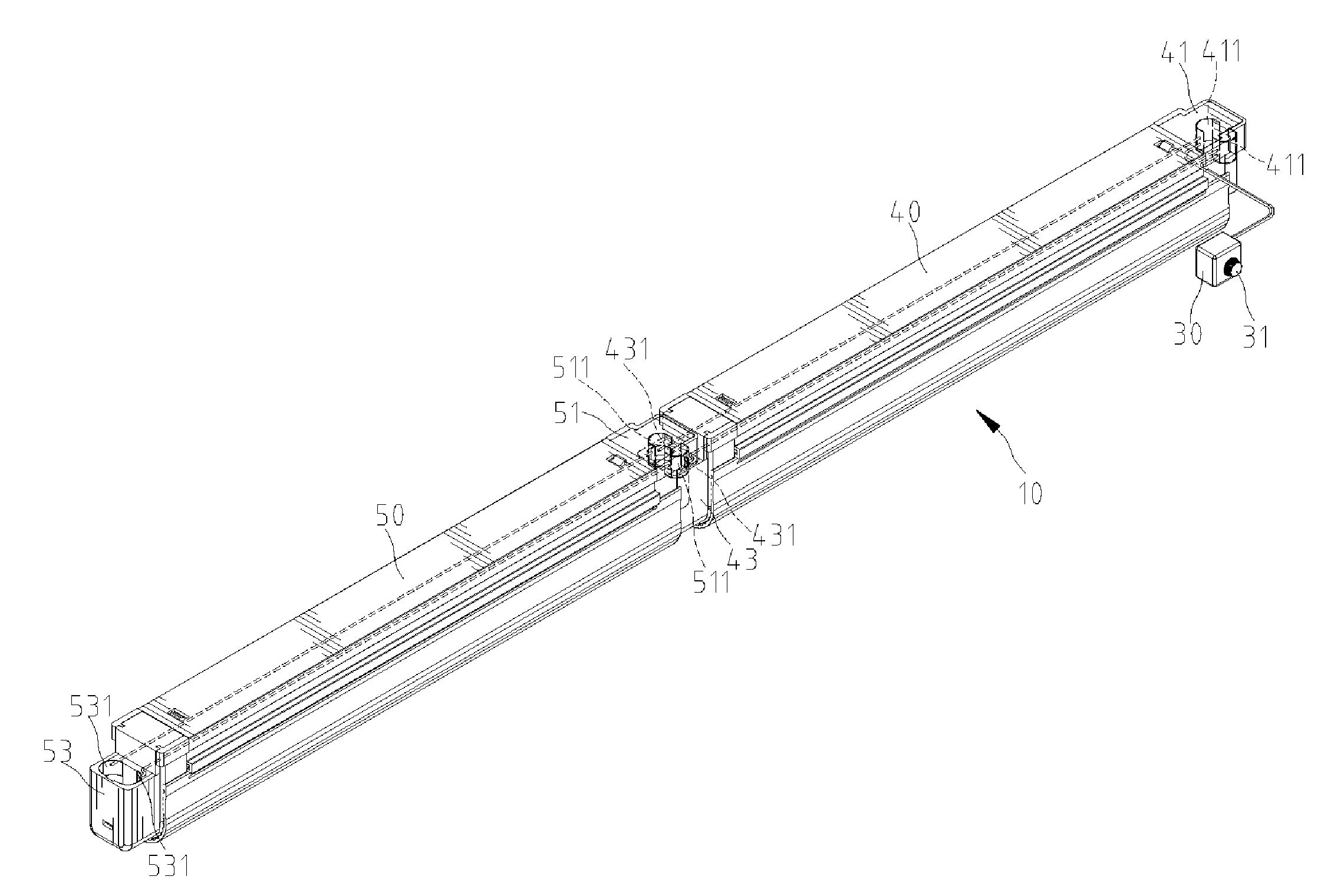
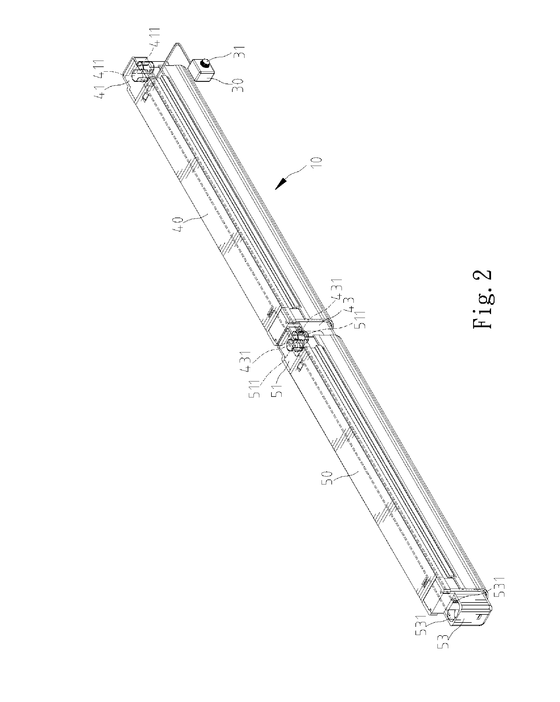
[0021]Shown in FIGS. 2 through 5 is a light array 10 according to a first embodiment of the present invention. The light array includes a major light 40, at least one minor light 50 connected to the major light 40 in parallel and a dimmer 30 connected to the major light 40.

[0022]The major light 40 includes a first connective unit 41 at an end and a second connective unit 43 at an opposite end. The first connective unit 41 is preferably an 8-figured plug extending perpendicular to the major light 40. The second connective unit 43 is preferably an oval socket defined in perpendicular to the major light 40. A lamp 44 is provided between the ends of the major light 40. The major light 40 is provided with a ballast 42. The first connective unit 41 can be connected to an alternating current (or “AC”) power supply. The first connective unit 41 includes two conductive elements 411 that are preferably U-shaped elements of copper. The second connective unit 43 includes two conductive elements...

Example

[0027]Shown in FIGS. 6 through 8 is a light array 60 according to a second embodiment of the present invention. The light array includes a major light 70, at least one minor light 80, a dimmer 90 connected to the major light 70 and at least one connector 100 for connecting the minor light 80 to the major light 70 in parallel.

[0028]The major light 70 include a first connective unit 71 at an end and a second connective unit 73 at an opposite end. The first connective unit 71 can be connected to an AC power supply. The first connective unit 71 includes two conductive elements 711 that are preferably U-shaped elements of copper. The second connective unit 73 includes two conductive elements 731 that are preferably arched elements of copper.

[0029]The dimmer 90 is energized by DC from at least one battery installed thereon. The dimmer 90 includes a knob 91 operable to adjust the luminance of the light emitted from each light of the light array 60.

[0030]The minor light 80 include a first c...


PUM


Abstract

A light array includes a major light, at least one minor light and a dimmer. The minor light is connected to the major light. The dimmer connected to the major light. The dimmer is operable for adjusting the luminance of light emitted from the major and minor lights.

Description

BACKGROUND OF INVENTION[0001]1. Field of Invention[0002]The present invention relates to an illuminative apparatus and, more particularly, to a light array.[0003]2. Related Prior Art[0004]Referring to FIG. 1, a conventional light array includes a plurality of lights. Each of the lights includes two connective units, two sockets 5 connected to the connective units, a light tube 7 with two terminal portions inserted in the sockets 5, a transparent tube 1 for covering the light tube, two rings 6 for holding the light tube 7 firmly in the transparent tube 1 and two pairs of caps 2 for covering the ends of the transparent tubes 1. Each of the caps 2 includes a plurality of rods inserted in apertures defined in the transparent tube 1. Each connective unit of a light can be used to receive a plug 8 leading to a power supply or a plug leading to a connective unit of another light. Problems have been encountered the assembly and use of this conventional light array. Firstly, it is troublesom...

Claims


Application Information

Patent Timeline
IPC IPC(8): B60Q1/26
CPCF21S4/003F21V21/005F21Y2103/00F21V23/06F21V23/04F21S4/20
Inventor HENDRIKUS, WESTERVELD JOHANNES
Owner OMNILUX LIGHTING
Why Eureka
Try Eureka