LED light-dimming driving circuit

A dimming drive and circuit technology, applied in circuit devices, lamp circuit layout, emergency protection circuit devices, etc., can solve the problems of complex circuits, high cost, easy damage, etc., and achieve the effect of high-efficiency structure and low cost

Active Publication Date: 2012-11-07
OCEANS KING LIGHTING SCI&TECH CO LTD +1
View PDF5 Cites 33 Cited by
  • Summary
  • Abstract
  • Description
  • Claims
  • Application Information

AI Technical Summary

Problems solved by technology

[0004] Although the switching circuit using DC / DC chopping technology has the advantages of low power consumption, high efficiency, stability and reliability, small unit power volume, light weight, etc., it has high cost, complex circuit, easy damage, and strong high frequency Disadvantages such as interference have brought inconvenience to users

Method used


Image

  • LED light-dimming driving circuit
  • LED light-dimming driving circuit

Examples


Embodiment Construction

[0025] In order to make the purpose, technical solution and advantages of the present invention clearer, an LED dimming driving circuit of the present invention will be further described in detail below in conjunction with the accompanying drawings and embodiments. It should be understood that the specific embodiments described here are only used to explain the present invention, not to limit the present invention.

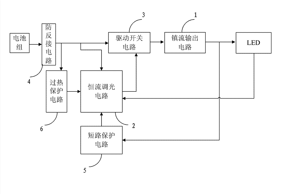
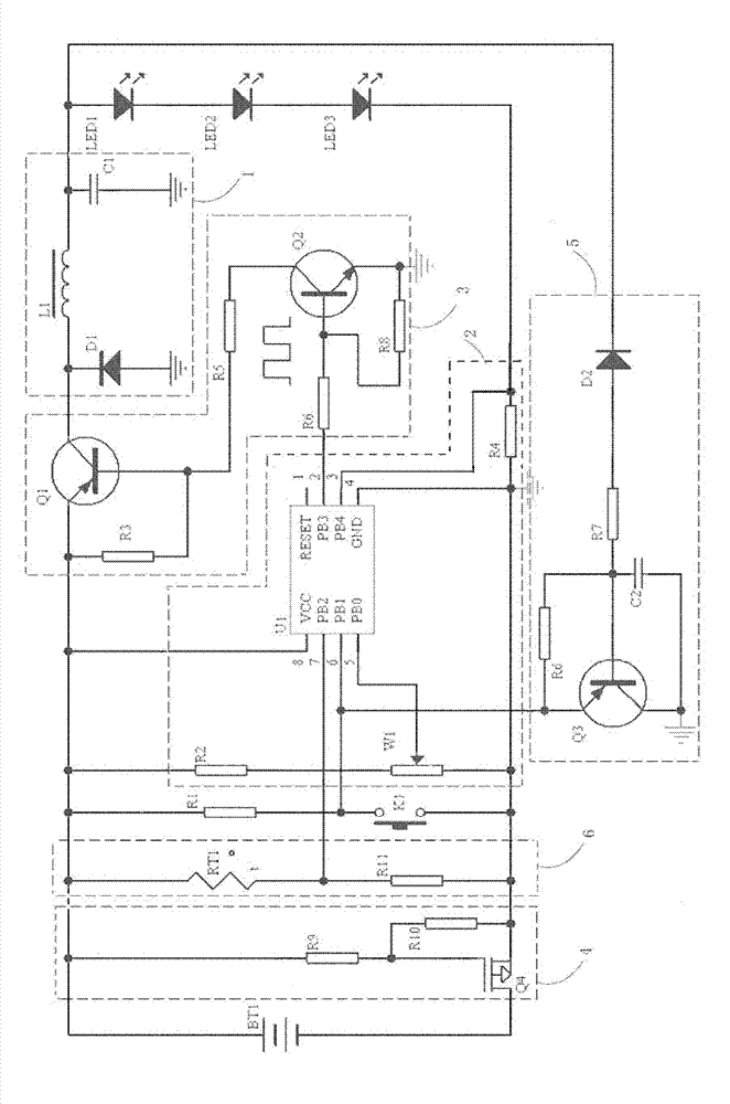
[0026] Such as figure 1 , the logical structure diagram of a specific embodiment provided by the present invention includes: battery pack BT1, LED light source, ballast output circuit 1, constant current dimming circuit 2, drive switch circuit 3, anti-reverse connection circuit 4, short circuit Protection circuit 5 and overheating protection circuit 6.

[0027] Further, the constant current dimming circuit 2 is used to output a control signal to the driving switch circuit 3, so that the driving switching circuit 3 drives the LED to emit light according to the con...


PUM


Abstract

The invention provides an LED light-dimming driving circuit comprising a short-circuit protection circuit, a ballast output circuit and a constant-current adjusting circuit. The LED light-dimming driving circuit is characterized by further comprising a driving switch circuit. The constant-current adjusting circuit comprises a single-chip microcomputer U1, a current sampling resistor R4, a light-dimming potentiometer W1 and a pressure parting resistor R2. A signal output pin of the single-chip microcomputer U1 outputs PWM (pulse width modulation) pulse signals, so that a driving triode Q2 and a switch triode Q1 are cut off or put through and lighting of LEDs can be controlled. The single-chip microcomputer U1 adjusts the PWM pulse signals output by the signal output pin according to feedback current. By the LED light-dimming driving circuit which is low in cost, simple in structure and efficient, the LED circuit is adjustable in luminance when at constant current state. Meanwhile, overheat protection, short-circuit protection and reverse-connection prevention function are added to the LED light-dimming driving circuit, so that stability, reliability and universality of the LED light-dimming driving circuit are improved.

Description

technical field [0001] The invention belongs to the field of LED lighting, and in particular relates to an LED dimming drive circuit. Background technique [0002] At present, in the field of lighting, DC-DC chopping technology is used to drive LEDs in low-voltage places; at present, DC / DC chopping technology is used in the driving circuit of LEDs in low-voltage places. [0003] The chopper circuit originally refers to "cutting off" a part of the sine wave due to a certain need in the application of electricity. (For example, when the voltage is 50V, use electronic components to cut off the 50-0V part behind, and the output voltage is 0.) Later, it was borrowed into the DC / DC switching circuit, mainly in the process of voltage regulation of the switching power supply. The power supply is "chopped" by the line into pulses one by one. [0004] Although the switching circuit using DC / DC chopping technology has the advantages of low power consumption, high efficiency, stabilit...

Claims


Application Information

Patent Timeline
Patent Type & Authority Applications(China)
IPC IPC(8): H05B37/02H02H5/04H02H3/08H02H11/00
Inventor 周明杰黄柯青
Owner OCEANS KING LIGHTING SCI&TECH CO LTD
Why Eureka
Try Eureka