Automatic frequency tracking method of supersonic transducer and system thereof

An automatic frequency tracking, ultrasonic transducer technology, applied in the direction of the fluid using vibration, can solve the problem that the transducer cannot fully release the power input signal, the duty cycle is relatively high, and the frequency tracking accuracy is low.

Active Publication Date: 2009-07-01
BEIJING ANHEJIALIER TECH CO LTD
View PDF2 Cites 48 Cited by
  • Summary
  • Abstract
  • Description
  • Claims
  • Application Information

AI Technical Summary

Problems solved by technology

[0007] The purpose of the present invention is to solve the problem that the transducer cannot fully release the power and the duty ratio of the phase comparator to the two input signals due to the low precision of the frequency tracking that exists in the automatic frequency tracking scheme using a phase-locked loop circuit A relatively demanding problem, thus providing an automatic frequency tracking method and system for ultrasonic transducers

Method used


Image

  • Automatic frequency tracking method of supersonic transducer and system thereof
  • Automatic frequency tracking method of supersonic transducer and system thereof
  • Automatic frequency tracking method of supersonic transducer and system thereof

Examples


Embodiment Construction

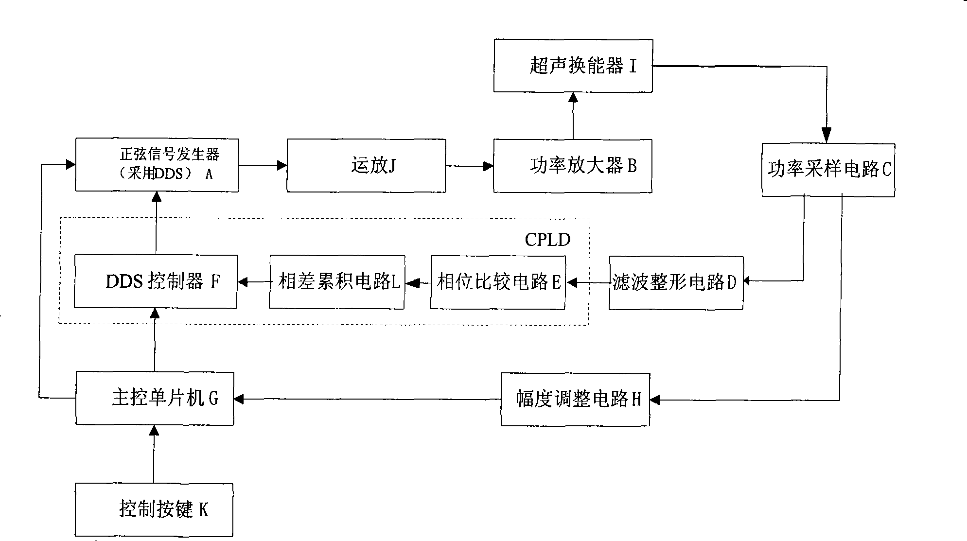
[0050] The design of the present invention is based on the principle that the excitation voltage and current of the ultrasonic transducer have the same phase at its resonant frequency point, and adopts the most advanced direct digital synthesis (DDS) and large-scale programmable devices to realize a novel fully Digital automatic frequency tracking solution.

[0051] The specific all-digital features are mainly manifested in:

[0052] ① The DDS as the excitation source of the transducer is controlled by an all-digital serial communication method.

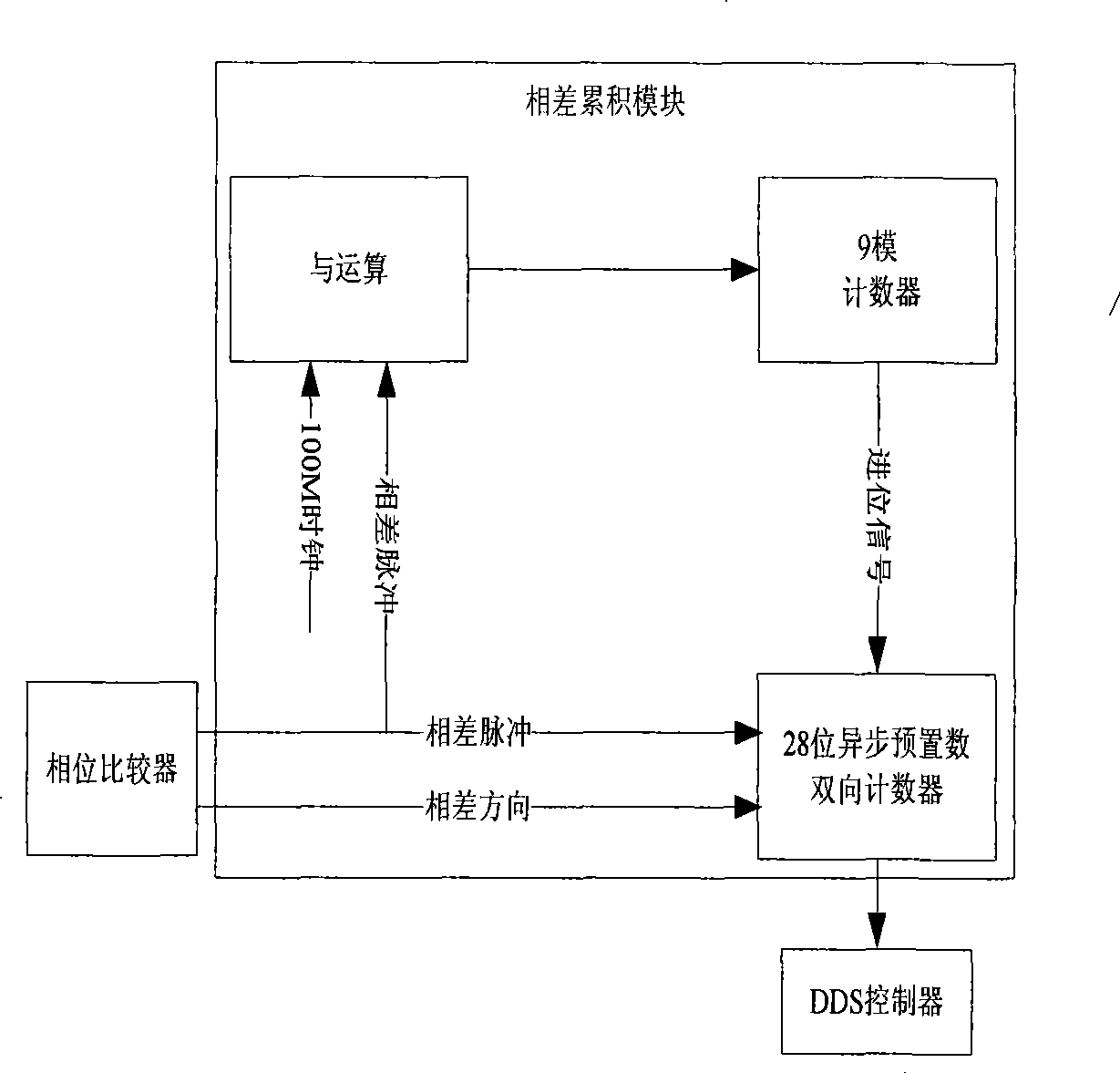
[0053] The phase difference signal given by the phase comparator is digitally processed and then fed back to the DDS to achieve frequency tracking, such as image 3 shown.

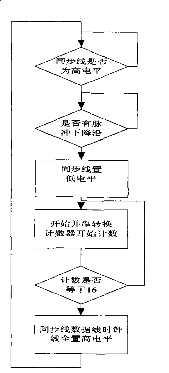
[0054] The core technology of the present invention is mainly the design of the DDS controller F and the phase comparator E which is only sensitive to the signal edge. The program flow chart of DDS controller F, such as figure 2 shown.

[0055] General bloc...


PUM


Abstract

The invention relates to an automatic frequency tracking method and a system for an ultrasonic transducer. A direct digital frequency synthesizer is used as a signal source, wherein the direct digital frequency synthesizer can be an independent integrated chip and also be achieved by the method that a digital part of a DDS is integrated in a site programmable logical element FPGA and then a digital-analog converter is additionally added. The design of the invention adopts a frequency sweeping and tracking policy, and an automatic frequency controller achieved by the programmable element controls the output frequency of the DDS according to a feedback signal sampled from the self transducer end so as to achieve the full digitization automatic frequency tracking and ensure that the ultrasonic transducer work near a resonance point all the time to obtain the optimal efficiency. A phase comparator utilizes a trigger to give out the arriving time difference of two riser edge signals of two input signals I ph and V ph aiming to the sensitive characteristics of the riser edge signals, and the sequence of the riser edge signals of the two input signals I ph and V ph is given out by a Dirrect pin.

Description

technical field [0001] The invention relates to the field of ultrasonic transducers, in particular to an automatic frequency tracking method and system for ultrasonic transducers. Background technique [0002] A typical ultrasonic transducer has a high quality factor (Q value) and a steep resonance curve. Only when it works at its resonance frequency point can it have a large mechanical amplitude and high motor conversion efficiency. Therefore, the driving circuit of the ultrasonic transducer should be excited with its resonant frequency signal. [0003] However, the resonant frequencies of practical transducers are often discrete and varying. This is because: (1) the difference in materials and processes in the manufacturing process of the transducer; (2) the change of the load characteristics matched by the transducer; (3) the parameters of the transducer itself change with time and temperature during use. Wait for changes. Therefore, the driving circuit of the transduc...

Claims


Application Information

Patent Timeline
Patent Type & Authority Applications(China)
IPC IPC(8): B06B1/02
Inventor 李平汪东李小雪肖灵
Owner BEIJING ANHEJIALIER TECH CO LTD
Why Eureka
Try Eureka