Photosensitive drum driving assembly

A photosensitive drum driving and photosensitive drum technology, applied in optics, electrographics, instruments, etc., can solve problems such as loss of drive connection function, ball-type universal joint disengagement, unstable operation, etc., to achieve simple assembly and reliable performance. , the effect of stable work

Active Publication Date: 2010-12-08
PRINT RITE UNICORN IMAGE PROD CO LTD OF ZHUHAI
1 Cites 46 Cited by

AI-Extracted Technical Summary

Problems solved by technology

This kind of drive connection structure has the following disadvantages: the ball universal joint is easy to come out of the gear (especia...

Method used

Referring to Fig. 11, there is transmission ring gear 24 on the outer peripheral surface of gear 2, and gear 2 interior is provided with vertical dividing plate 25 and the gear chamber 21 that is positioned at dividing plate 25 tops, and the center of this dividing plate 25 There is a drum-shaped hole 22 at the position, the width of the drum-shaped hole 22 is substantially equal to the cross-sectional width of the rod portion 52 of the adjustment rod 5 , and its length is greater than the cross-sectional length of the rod portion 52 . A plurality of ribs 23 extending in th...

Abstract

The invention provides a photosensitive drum driving assembly which comprises a gear wheel and an adjusting assembly, wherein the gear wheel is closely fitted at one end of a photosensitive drum; the adjusting assembly comprises a rotary driving force receiving head which extends out of the gear wheel; the adjusting assembly can be arranged in the gear wheel to move in reciprocating translation relative to the gear wheel along the axial direction of the photosensitive drum and a first direction vertical to the axial direction, and an elastic support part and an axial limit part are arranged between the adjusting assembly and the gear wheel; and the rotation driving force receiving head can be rotatably arranged on the adjusting assembly around the axis per se. Compared with the prior art, the photosensitive drum driving assembly allows simple and convenient assembly, and has stable structure performance; and a processing box in which the photosensitive driving assembly is adopted ensures stable disembarking and stable operation and has reliable performance.

Application Domain

Electrographic process

Technology Topic

Image

  • Photosensitive drum driving assembly
  • Photosensitive drum driving assembly
  • Photosensitive drum driving assembly

Examples

  • Experimental program(1)

Example Embodiment

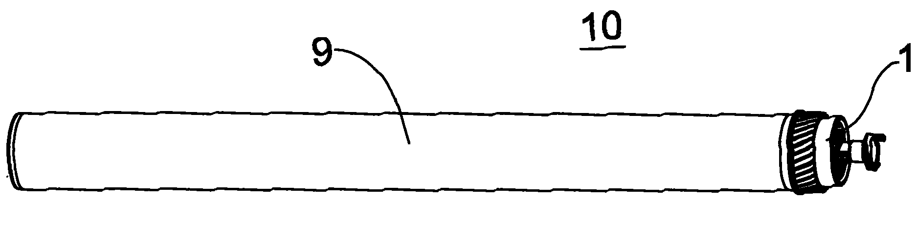
[0040] figure 1 Shown is a photosensitive drum 10 to which a driving assembly 1 according to an embodiment of the present invention is applied. The driving assembly 1 is fixed at one end of the drum main body 9 of the photosensitive drum 10. The peripheral surface of the drum main body 9 has a photosensitive layer. The driving assembly 1 is used to receive the rotational driving force from the printer driving mechanism, and transmit the rotational driving force to the drum main body 9, so that the drum main body 9 rotates around its axis under the action of the rotational driving force.
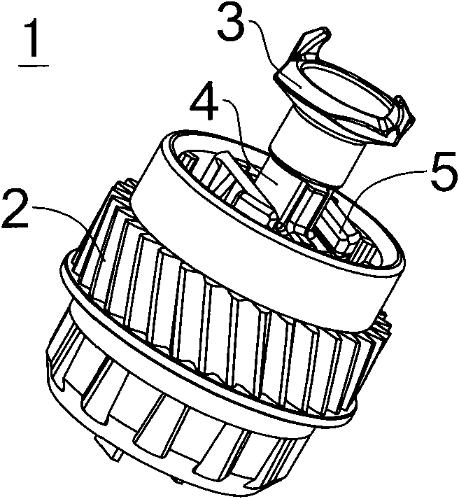
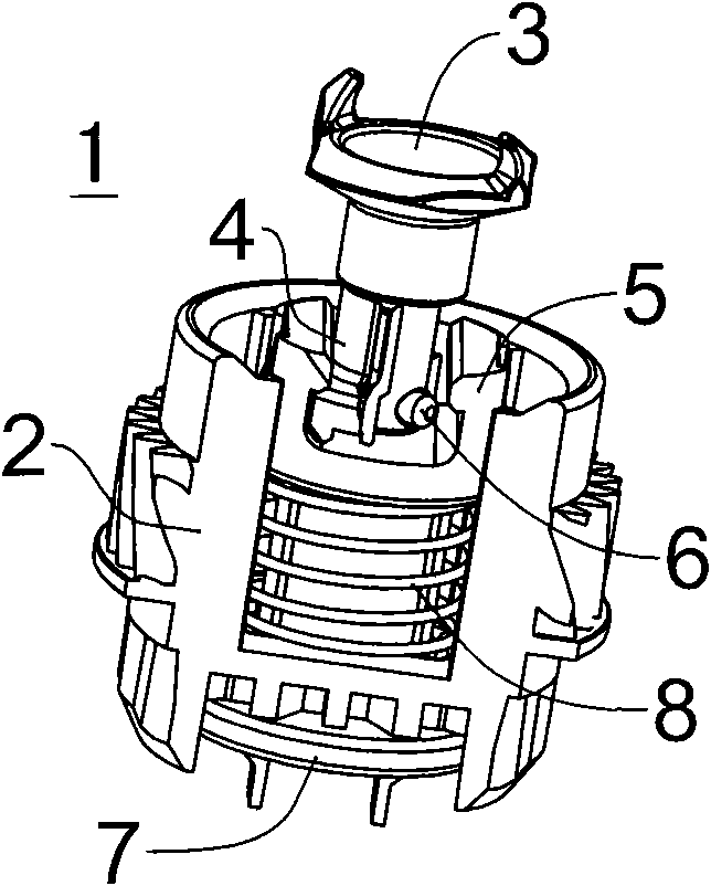
[0041] Figure 2 ~ Figure 4 The basic composition of the driving assembly 1 is shown, and its structure mainly includes a gear 2 , a rotating driving force receiving head 3 , an adjusting slider 4 , an adjusting rod 5 , a rotation limiting pin 6 , a limiting bottom plate 7 and a helical compression spring 8 . The gear 2 is closely matched with one end of the drum main body 9, the axis of the gear 2 coincides with the axis of the drum main body 9, and rotates around their common axis synchronously with the drum main body 9. The rotating driving force receiving head 3 is connected to the adjusting slider 4 through the rotation limit pin 6, and the rotating driving force receiving head 3 can reciprocate around its axis within a certain angle range relative to the adjusting sliding block 4; Slot 55 , the adjustment slider 4 can reciprocally slide relative to the adjustment rod 5 in the chute 55 ; the spring 8 is sleeved on the adjustment rod 5 ;
[0042]Wherein, the rotating driving force receiving head 3 , the adjusting slider 4 , the rotation limiting pin 6 and the adjusting rod 5 constitute an adjusting assembly 11 . see Figure 19a ~ Figure 19c , through the compression of the spring 8 and the axial limitation of the limiting bottom plate 7, the adjustment assembly 11 can perform limited axial reciprocating translational movement relative to the gear 2 along the axial direction Z of the photosensitive drum. see you again Figure 16 , 17 、18a~ Figure 18c , the adjustment assembly 11 can also perform a limited first linear reciprocating translational movement relative to the gear 2 along the first direction X perpendicular to the axial direction Z of the photosensitive drum, and this movement is realized in the drum-shaped hole 22 of the gear 2 of. Also see you again Figure 13 ~ Figure 17 , the movement sub-assembly 12 composed of the rotating driving force receiving head 3, the adjusting slider 4 and the rotating limit pin 6 can move relative to the adjusting rod in the chute 55 along the second direction Y perpendicular to the axial direction Z of the photosensitive drum. 5. Perform a limited second linear reciprocating translational movement. The projections of the first direction X and the second direction Y on the same radial plane of the photosensitive drum 10 are in a state of intersecting each other, neither overlapping nor parallel. In this embodiment, the first direction X and the second direction Y are mutually vertical.
[0043] see Figure 5 and Image 6 , the rotating driving force receiving head 3 is roughly in the shape of a torch, from outside to inside ( Figure 5 In the middle, the outer end portion 30, the middle portion 36 and the shaft portion 37 that are tapered successively from top to bottom are formed, and the middle portion 36 and the shaft portion 37 are all cylindrical, and the shaft portion 37 is provided with a rotation limiting pin 6 to pass through. The pin hole 38. A concave spherical surface 35 is formed at the center of the outer end 30, and a first protruding claw 31 and a second protruding claw 32 are formed around the spherical surface 35. The first protruding claw 31 and the second protruding claw 31 The pawl 32 forms a central symmetry with respect to the axis 39 of the rotational driving force receiving head 3 . In addition, a first cut plane 33 and a second cut plane 34 which are separated by the first lug 31 and the second lug 32 and are also centrally symmetrical about the axis 39 are formed around the spherical surface 35 . The surface of the first lug 31 has a first occlusal surface 313, a first bevel 311 and a second bevel 312, and the surface of the second lug 32 has a second occlusion surface 323, a third bevel 321 and a fourth bevel 322, wherein, The first occlusal surface 313 and the second occlusal surface 323, the first slant 311 and the third slant 321, the second slant 312 and the fourth slant 322 respectively form a central symmetry about the axis 39, the first slant 311, the second slant 312, the second slant Both the three slopes 321 and the fourth slope 322 are formed on the outer peripheral edge of the rotational driving force receiving head 3 .
[0044] see Figure 7 and Figure 8 , the adjustment slider 4 is composed of a substantially drum-shaped base 46 and a cylindrical boss 45 formed on the base 46, the boss 45 has a cylindrical through hole 47 axially penetrating inside, the through hole 47 The diameter is larger than the diameter of the shaft portion 37 of the rotational driving force receiving head 3 and smaller than the diameter of the middle portion 36 of the rotational driving force receiving head 3, so that only the shaft portion 37 can pass through. The first side 48 of the base 46 has a first limiting protrusion 41 extending outward, and the second side 49 has a second limiting protrusion 49 extending outward. The functions of the two limiting protrusions are Control the distance that the adjustment slide block 4 moves in the plane of the adjustment rod chute. On the bottom surface of the base 46, there is a groove 410 for accommodating the rotation limiting pin 6. The groove 410 is formed around the through hole 47, and two opposite first limit stops 43 and second limit stops are arranged in the groove. The stopper 44 enables the rotation limiting pin 6 to rotate around the axis 411 of the adjustment slider 4 within a certain angle range.
[0045] see Figure 9 and Figure 10 The adjustment rod 5 is composed of a top 51, a rod portion 52 and a snap ring 53. The projection of the top 51 on its radial plane is circular, and the top 51 has a slide groove 55 penetrating in the radial direction. The slide groove 55 The cross section is roughly "convex" shape. The adjustment slide block 4 can slide radially in the slide groove 55 . The cross-sectional shape of the rod portion 52 is a drum shape. The snap spring 53 is substantially in the shape of a "U" with claws 54 formed thereon.
[0046] see Figure 11 , the outer peripheral surface of the gear 2 has a transmission ring gear 24, and the inside of the gear 2 is provided with a partition 25 perpendicular to the axial direction and a gear cavity 21 above the partition 25, and a drum-shaped hole is opened in the center of the partition 25 22 , the width of the drum-shaped hole 22 is substantially equal to the cross-sectional width of the rod portion 52 of the adjusting rod 5 , and its length is greater than the cross-sectional length of the rod portion 52 . A plurality of ribs 23 extending in the axial direction are evenly distributed on the circumferential side wall 26 of the gear cavity 21 , and the function of the ribs 23 is to enhance the strength of the inner wall of the gear 2 . see Figure 16 and Figure 17 , the drum-shaped hole 22 provides a limit for the first linear reciprocating translational movement of the adjustment assembly 11 along the direction X, while the circumferential side wall 26 and rib 23 of the gear chamber 21 provide a limit for the movement subassembly 12 along the direction Y. The second linear reciprocating translational movement provides a limit.
[0047] see Figure 12 , The limiting bottom plate 7 is a circular plate, and the limiting bottom plate 7 is provided with two clamping holes 71, 72 through which the clip spring 53 of the adjusting rod 5 can pass.
[0048] see Figure 13 and Figure 14 , the motion subassembly 12 is made up of the rotating driving force receiving head 3, the adjusting slider 4 and the rotating stop pin 6, the shaft part 37 of the rotating driving force receiving head 3 passes through the through hole 47 of the adjusting slider 4, and the rotating limiting pin 6 passes through the pin hole 38 of the shaft portion 37 and is placed in the groove 410 at the bottom of the adjustment slider 4 .
[0049] see Figure 15 , The adjustment assembly 11 is composed of the rotational driving force receiving head 3 , the adjustment slider 4 , the rotation limit pin 6 , the adjustment rod 5 and the limit plate 7 . Through the compression of the spring 8 , the adjustment assembly 11 can perform axial reciprocating translational movement relative to the gear 2 along the axis Z of the photosensitive drum.
[0050] pass Figure 16 and Figure 17 , the positional relationship between the adjustment assembly 11 and the gear 2 can be clearly understood. For ease of understanding, Figure 16 The rotary driving force receiving head 3 is hidden in the Figure 17 Hidden limit base plate 7 in.
[0051] pass Figure 18a ~ Figure 18c , it can be clearly understood that the first linear reciprocating translational movement of the adjustment assembly 11 relative to the gear 2 along the first direction X perpendicular to the axial direction Z of the photosensitive drum is realized in the drum-shaped hole 22 of the gear 2 of.
[0052] pass Figure 19a ~ Figure 19c , it can be clearly understood that the adjustment assembly 11 performs an axial reciprocating translational movement relative to the gear 2 along the axis Z of the photosensitive drum through the compression of the spring 8 .
[0053] Figure 20a ~ Figure 20d A schematic diagram showing the working process of the process cartridge (only showing the end of the photosensitive drum) with the drive assembly 1 falling into the printer, the process cartridge falls into the printer along the direction Xa perpendicular to the axis of the photosensitive drum; Figure 21a ~ Figure 21d A schematic diagram showing the process of removing the process cartridge equipped with the drive assembly 1 from the printer, the process cartridge is removed from the printer along the direction Xb perpendicular to the axis of the drum. The adjustment part 11 in the driving assembly 1 moves inwards along the direction Za as a whole, and the adjustment part 11 moves outwards along the direction Zb as a whole; see Figure 13 , θa represents the clockwise rotation direction of the rotational driving force receiving head 3, and θb represents the counterclockwise rotation direction of the rotational driving force receiving head 3.
[0054] Its working process is as follows:
[0055] 1. Push the process cartridge into the printer along the direction Xa;
[0056] 2. See Figure 20a ~ Figure 20d , when the drive assembly 1 on the process cartridge is put into the printer along the direction Xa and touches the drive rod 13 of the printer, there are two situations that need to be disassembled and explained:
[0057] 1) If the initial contact position is the first claw 31, the printer driving lever 13 will touch the two slopes 311, 312 of the first claw 31, and one of the two surfaces must be weaker in force. When the force on the slope 312 is weak, the printer drive rod 13 rubs against the second slope 312 to push the rotary driving force receiving head 3 to rotate an angle along the direction θa, and the printer drive rod 13 will automatically cut into the first slope adjacent to the second slope 312. on the two tangent planes 34, and cause the adjustment assembly 11 in the driving assembly 1 to move along the Za direction as a whole; when the force on the first inclined surface 311 is weak, the printer driving rod 13 will rub against the first inclined surface 311 to push the rotating driving force receiving head. 3 After turning an angle along the θb direction, the printer driving lever 13 will automatically cut into the first cut plane 33 adjacent to the first slope 311, and cause the adjustment assembly 11 in the driving assembly 1 to move along the Za direction as a whole. Since the second claw 32 is symmetrical to the center of the first claw 31, when the initial contact position is the second claw 32, its action process is similar to the above process;
[0058] 2) If the initial contact position is the first cut surface 33 or the second cut surface 34, the printer driving rod 13 will directly and automatically cut into the first cut surface 33 or the second cut surface 34, and cause the entire adjustment assembly 11 in the drive assembly to Move in the Za direction.
[0059] 3. As the force along the direction Xa increases, the overall displacement of the adjustment assembly 11 in the drive assembly 1 along the Za direction also increases; and only when the printer drive rod touches the spherical surface 35, the adjustment components in the drive assembly 1 11 The whole moves along the direction Zb until the displacement is zero;
[0060] 4. When the printer is started, the printer driving lever 13 will automatically couple the rotating driving force receiving head 3, and the rotating driving force receiving head 3 receives the rotating driving force from the printer to drive the drum main body 9 of the photosensitive drum 10 to rotate;
[0061] 5. When the rotating driving force receiving head 3 receives the driving force of the printer, the driving force from the printer may not be a constant value, so the adjusting component 11 in the driving component 1 moves linearly in a small range to buffer the driving force of the printer Change the value, so that the photosensitive drum rotates smoothly without jumping and fluctuations, the process cartridge works normally, and the printing quality is excellent;
[0062] 6. See Figure 21a ~ Figure 21d , when the printer stops running, when the process cartridge is taken out from the printer, the process cartridge moves initially along the direction Xb, and the printer driving rod 13 starts to break away from the rotating driving force receiving head 3;
[0063] 7. When the printer drive rod 13 touches the edge of the spherical surface 35, the adjustment assembly 11 in the drive assembly 1 starts to move along the direction Za as a whole;
[0064] 8. As the overall displacement of the adjustment assembly 11 increases along the direction Za, if the printer driving lever encounters the first claw 31 or the second claw 32, it will pull the rotating driving force receiving head 3 along the θa or θb direction Turn an angle, causing the printer driving rod 13 to cut into the first cut plane 33 or the second cut plane 34;
[0065] 9. When the printer drive rod 13 cuts into the first tangent plane 33 or the second tangent plane 34, the adjustment assembly 11 as a whole starts to move along the direction Zb until the displacement reaches zero, and the process cartridge can be taken out of the printer.
[0066] The above are only preferred embodiments of the present invention. It should be pointed out that for those skilled in the art, without departing from the concept of the present invention, some modifications and improvements can be made without departing from the scope of the claims of the present invention. protected range. For example, the limiting bottom plate can be realized by adopting other axial limiting structures that those skilled in the art can easily think of. The axial limiting structure can be an independent component separated from the adjusting rod, or can be a part formed on the adjusting rod. In addition, the elastic support member can be replaced by an elastic member other than a helical compression spring, such as a compressible elastic plastic part structure, etc.; the shape of the limiting hole on the separator of the gear is not limited to a drum shape, and can also be a rectangle Any shape with two flat sides, such as a planar quadrilateral, as long as the adjustment assembly can only translate in the axial and radial directions, but cannot rotate around the axis.

PUM

no PUM

Description & Claims & Application Information

We can also present the details of the Description, Claims and Application information to help users get a comprehensive understanding of the technical details of the patent, such as background art, summary of invention, brief description of drawings, description of embodiments, and other original content. On the other hand, users can also determine the specific scope of protection of the technology through the list of claims; as well as understand the changes in the life cycle of the technology with the presentation of the patent timeline. Login to view more.

Similar technology patents

Viscoelastic damping anti-galloping device

InactiveCN103701079AGuaranteed Stability and ReliabilityGood energy consumptionDevices for damping mechanical oscillationsPistonTransmission line
Owner:CHINA ELECTRIC POWER RES INST +1

Classification and recommendation of technical efficacy words

  • Guaranteed stability and reliability
  • Easy assembly

Gas sensor

Owner:RAE SYST SHANGHAI
Why Eureka
Try Eureka