Sludge drying equipment

A sludge drying and equipment technology, applied in the direction of dehydration/drying/concentrated sludge treatment, etc., can solve the problems of poor dehumidification efficiency, inability to dry thoroughly, and no proper dust separation measures, etc., and achieve high drying efficiency

Inactive Publication Date: 2014-02-19
HEFEI HUANKUN SLUDGE DRYING EQUIP
View PDF6 Cites 10 Cited by
  • Summary
  • Abstract
  • Description
  • Claims
  • Application Information

AI Technical Summary

Problems solved by technology

Among them, the direct heat transfer sludge dryer is described in the invention patent "Sludge Drying Process and Equipment" filed by the applicant Suzhou Zili Chemical Equipment Co., Ltd. on June 22, 2010. Most of them use high-temperature flue gas from the boiler as the heat source, making it directly contact with the wet sludge after entering the dryer, and directly bring out the moisture in the wet sludge through heat convection; this method has high dehumidification efficiency, but due to a large amount of The direct contact and precipitation of flue gas and wet sludge leads to a huge amount of dust in the waste heat of fly ash, and without proper follow-up dust separation measures, it is often prone to safety hazards such as dust explosions
In the indirect heat transfer sludge dryer, the sludge and the heat source are not in direct contact, but heat is transferred through heat conduction. For example, the applicant is the invention patent "Sludge Drying and Incineration" applied by Zhejiang University on April 19, 2012 "Integrated Treatment System and Its Process" provides an indirect heat transfer sludge drying method. Since the sludge and the heat source are artificially separated, the heating flue gas has good cleanliness and no related dust hazards. Therefore, it is used However, due to the current indirect heat transfer dryer or the use of static baking methods similar to pots and stoves, the sludge settles under the action of gravity and single-sided heating occurs, and the heating is not uniform enough, resulting in The sludge to be treated cannot be dried evenly, and the dehumidification efficiency is poor. Even if the fixed and movable teeth are staggered and the movable teeth are designed as hollow flues in the aforementioned patent text, this method not only leads to a complex and cumbersome structure, but also makes maintenance extremely inconvenient. At the same time, it will also cause a large amount of sludge to accumulate in the lower chamber of the fixed teeth, which will cause the phenomenon that it cannot be dried through and directly sintered. In addition, since the tooth surface of the movable teeth is set perpendicular to the direction of the rotation axis, how to ensure that the sludge is dried The final discharge purpose is obviously not conclusively realized in terms of its mechanism; in addition, the current sludge dryer, because its sludge containing chamber always needs to frequently contact or dry or wet sludge, its friction after severe friction The wear rate of the housing cavity is extremely high, and the service life often affects the actual use efficiency of the whole machine

Method used


Image

  • Sludge drying equipment
  • Sludge drying equipment
  • Sludge drying equipment

Examples


Embodiment Construction

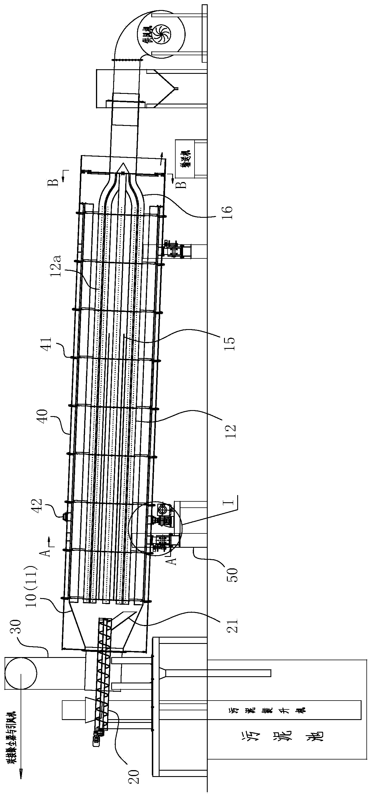
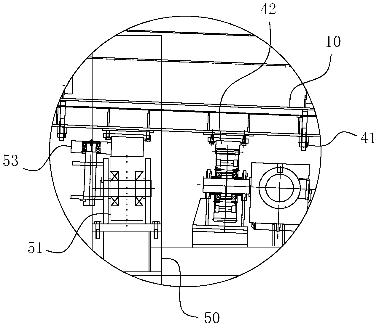
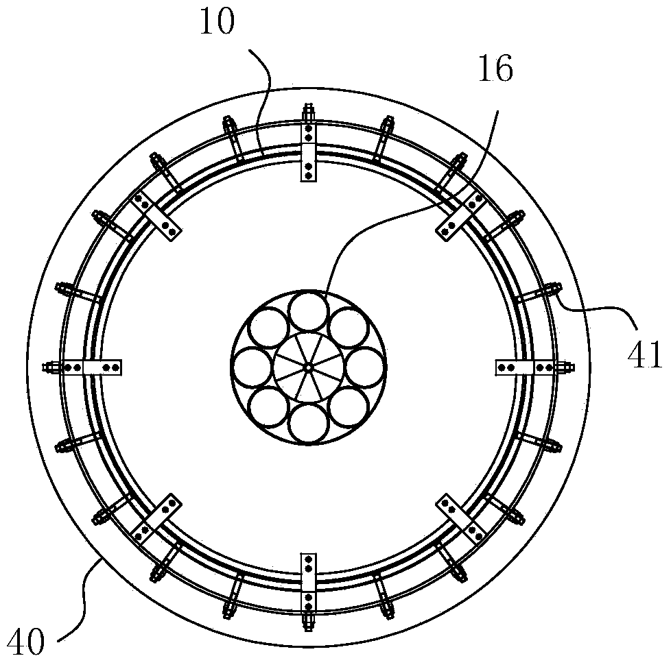
[0038] For ease of understanding, combined here Figure 1-4 Specifically set forth the component structure of the present invention and its specific work flow:

[0039] Concrete structure of the present invention, as Figure 1-4 As shown, it generally includes an outer shell 40, a support frame 50 is arranged on the outer wall of the outer shell 40, and a rolling support roller assembly is correspondingly arranged at the support frame 50, including a support roller 52 and a support roller 51, and the support roller assembly is arranged on the support frame 50 on the column, while the support frame 14 is positioned at the side of the supporting roller 52 and the supporting roller 51, and an orientation wheel 53 is also arranged to ensure the actual rolling guide of the cylinder 10. A mud feeder is arranged at the high end of the outer shell 40, and a screw conveyor 20, etc. are used for specific operations; the mud feeder penetrates the outer shell 40 to communicate with the a...


PUM


Abstract

The invention belongs to the field of solid waste treatment, in particular relates to sludge drying equipment based on drying treatment of urban sludge. The sludge drying equipment comprises a drum with an inclined axis, and a driving assembly for driving the drum to rotate along the axis of the drum, wherein the drum is provided with an accommodating cavity for accommodating sludge; the accommodating cavity is arranged in the axial direction of the drum and in a penetrating manner; the feeding end of the accommodating cavity is arranged at the high end part of the drum, and the discharging end of the accommodating cavity is arranged at the lower end part of the drum; the sludge drying equipment further comprises heat supply pipes for supplying heat to the accommodating cavity; the heat supply pipes are arranged in the accommodating cavity; two or more heat supply pipes are arranged in the axial direction of the accommodating cavity; air vent holes communicated with the cavities of the heat supply pipes and the accommodating cavity are formed in the walls of the heat supply pipes. The heat supply pipes of the invention are used as stirring pipes of the whole accommodating cavity while performing the functions of supplying heat and drying. The sludge drying equipment has the advantages of simple structure, easy and reliable operation, effective achievement of purpose of drying existing wet sludge and extremely-high drying efficiency.

Description

technical field [0001] The invention belongs to the field of solid waste treatment, and in particular relates to sludge drying equipment based on urban sludge drying treatment. Background technique [0002] With the continuous acceleration of urbanization and the development of modern industry. Every year, a huge amount of various types of municipal domestic sludge and industrial sludge are produced all over the world. For this reason, people began to look for a suitable process to effectively treat the above sludge. Sludge drying technology is a common technology that can effectively reduce the moisture content of sludge so that it can continue to be processed. Specifically, it is the process of heating the sludge in specially designed equipment and evaporating the water in it. It can not only Effectively realize the removal effect of "free water" in the sludge, and at the same time, it can quickly evaporate the "interstitial water", "surface bound water" and even "intern...

Claims


Application Information

Patent Timeline
Patent Type & Authority Applications(China)
IPC IPC(8): C02F11/12
Inventor 李登平韩莹
Owner HEFEI HUANKUN SLUDGE DRYING EQUIP
Why Eureka
Try Eureka