Municipal sludge drying device

A technology of municipal sludge and oblique placement, applied in the direction of dehydration/drying/concentrated sludge treatment, etc., can solve the problems of poor dehumidification efficiency, frequent use, and inconvenient maintenance, and achieve the effect of reliable operation, high work efficiency, and simple structure

Inactive Publication Date: 2015-04-15
广州科理环保科技有限公司
View PDF3 Cites 0 Cited by
  • Summary
  • Abstract
  • Description
  • Claims
  • Application Information

AI Technical Summary

Problems solved by technology

Among them, the direct heat transfer sludge dryer is described in the invention patent "Sludge Drying Process and Equipment" filed by the applicant Suzhou Zili Chemical Equipment Co., Ltd. on June 22, 2010. Most of them use high-temperature flue gas from the boiler as the heat source, make it directly contact with the wet sludge after entering the dryer, and directly bring out the moisture in the wet sludge through heat convection; this method has high dehumidification efficiency, but Due to the direct contact and precipitation of a large amount of flue gas and wet sludge, the dust content in the fly ash waste heat is huge, and due to the lack of proper follow-up dust separation measures, it is often prone to safety hazards such as dust explosions
In the indirect heat transfer sludge dryer, the sludge and the heat source are not in direct contact, but heat is transferred through heat conduction. For example, the applicant is the invention patent "Sludge Drying" applied by Zhejiang University on April 19, 2012 "Incineration Integrated Treatment System and Its Process" provides an indirect heat transfer sludge drying method. Since the sludge and heat source are artificially separated, the heating flue gas has good cleanliness and no related dust hazards. Therefore, it is often used; however, due to the current indirect heat transfer dryer or the static baking method similar to a pot, the sludge settles inside under the action of gravity and one-sided heating occurs, and the heating is not uniform enough. , so that the sludge to be treated cannot be dried evenly, and the dehumidification efficiency is poor. Even if the fixed and movable teeth are interlaced and the movable teeth are designed as hollow flues in the aforementioned patent text, the method not only leads to a complicated and cumbersome structure. It is extremely inconvenient to maintain, and at the same time, it will cause a large amount of sludge to accumulate in the lower chamber of the fixed teeth, resulting in the phenomenon that it cannot be baked through and directly sintered. The purpose of discharging after drying is obviously impossible to realize in terms of its mechanism; in addition, the current sludge dryer, because its sludge containing chamber always needs frequent contact with dry or wet sludge, its After severe friction, the wear rate of the housing cavity is extremely high, and the service life often affects the actual use efficiency of the whole machine

Method used


Image

  • Municipal sludge drying device
  • Municipal sludge drying device
  • Municipal sludge drying device

Examples


Embodiment Construction

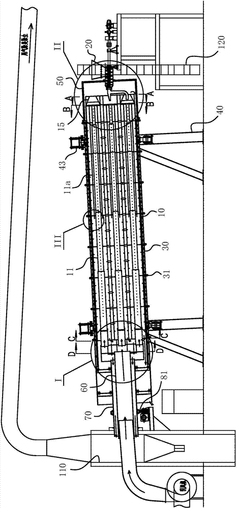
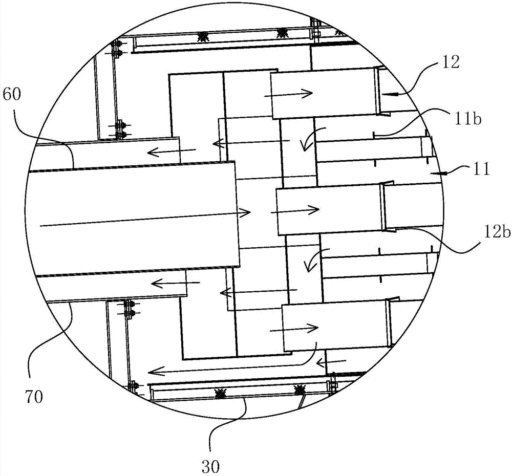
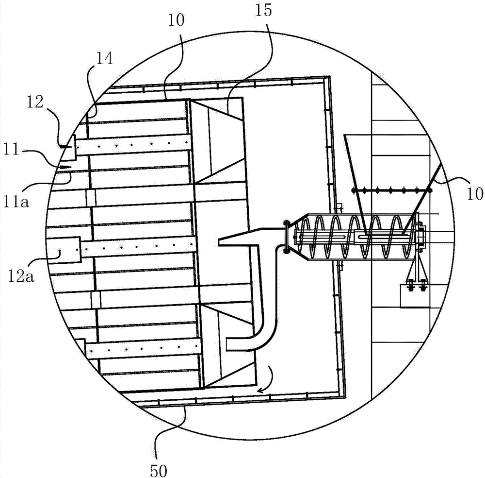
[0041] For ease of understanding, combined here Figure 1-8 Specifically set forth the component structure of the present invention and its specific work flow:

[0042] Actual finished product of the present invention, can refer to figure 1 As shown, it usually includes an outer drum (that is, an outer casing 30), and a support frame 40 is arranged outside the outer drum 30, and a rolling support roller assembly is correspondingly provided at the support frame 40, including a support roller 42 and a support roller 41, and the support roller The assembly is arranged on the column of the support frame 14 , and at the same time, the support frame 14 is also provided with directional wheels 43 to ensure the actual rolling guidance of the drum 10 . A return air cover 50 is arranged at a height of one end of the cylinder body of the outer drum, and the return air cover 50 is connected with the shell at the end of the outer drum. cavity), a mud supply machine is arranged at the end...


PUM


Abstract

The invention belongs to the field of solid waste treatment, and in particular relates to a municipal sludge drying device. The municipal sludge drying device comprises a roller with an axial line obliquely arranged and a driving component for driving the roller to rotate along the axial line thereof, wherein an accommodating cavity for accommodating sludge is formed in the roller; the accommodating cavity stretches and penetrates in an axial direction of the roller, and a feeding end of the accommodating cavity is positioned at the high end of the roller while a discharging end is arranged on the low end of the roller. Furthermore, the municipal sludge drying device comprises a heat supply passage for supplying heat to the accommodating cavity and an air return passage for collecting and removing fly ash waste heat after drying wet sludge, and the heat supply passage is arranged in a manner of communicating with the accommodating cavity; an air intake end of the air return passage is communicated with the accommodating cavity, and an air exhaust end is communicated with external fly ash waste heat treatment equipment. The municipal sludge drying device is high in sludge drying efficiency, and can avoid environmental pollution or even personal safety and other circumferences caused by a conventional device which discharges the fly ash waste heat along with the dry sludge; the municipal sludge drying device is concise in structure, reliable to operate, high in working efficiency, and safe and stable.

Description

technical field [0001] The invention belongs to the field of solid waste treatment, in particular to an urban sludge drying device. Background technique [0002] With the continuous acceleration of urbanization and the development of modern industry. Every year, a huge amount of various types of municipal domestic sludge and industrial sludge are produced all over the world. For this reason, people began to look for a suitable process to effectively treat the above sludge. Sludge drying technology is a common technology that can effectively reduce the moisture content of sludge so that it can continue to be processed. Specifically, it is the process of heating the sludge in specially designed equipment and evaporating the water in it. It not only It can effectively remove the "free water" in the sludge, and at the same time, it can quickly evaporate the "interstitial water", "surface bound water" and even "internal bound water"; because this technology can According to th...

Claims


Application Information

Patent Timeline
Patent Type & Authority Patents(China)
IPC IPC(8): C02F11/12
Inventor 李登平韩莹
Owner 广州科理环保科技有限公司
Why Eureka
Try Eureka