Method and system for the three-dimensional representation

a three-dimensional representation and display technology, applied in optics, instruments, electrical appliances, etc., can solve the problems of changing the image quality, and affecting the usability of the arrangemen

Inactive Publication Date: 2006-05-16
PHOENIX 3D INC
View PDF90 Cites 39 Cited by
  • Summary
  • Abstract
  • Description
  • Claims
  • Application Information

AI Technical Summary

Benefits of technology

[0008]In U.S. Pat. No. 5,938,774, structured light sources which can also be structured with respect to their spectral properties, among other things, are used as a basis for autostereoscopic display. These structured light sources work together with lens-like optical components which map or image upon determined regions of light modulators, for example, LC displays, a group of concentrations of light generated at determined intervals for each perspective view. The disadvantageous effects described above also occur in these arrangements.
[0009]For selecting the direction of the light proceeding from the perspective views, JP 10333090 suggests the use of color illumination and color filters. In addition, an optical filter is provided for reducing the amount of light in predetermined wavelength regions. The procedure described in this reference is a two-channel method based on only two perspective views, each view being perceivable to one eye of the observer. According to the disclosure, the width of a filter element or the width of an illumination element roughly corresponds to twice the width of a subpixel in an LC display. From this it necessarily follows that conventional LC displays are not applicable for generating the structured illumination, since an RGBRGBRGB color structure of the subpixels is predetermined in this display. Further, in this case too, the stripe-shaped color filters in periodic arrangement again inevitably give rise to Moiré fringes. The fixed distance between the observer and the image plane given by the indicated equations and functions is also disadvantageous.
[0010]U.S. Pat. No. 5,751,479 describes an autostereoscopic display in which wedge-shaped light propagation directions are predetermined by vertically extended stripe-shaped red, green and blue filters for views which are interlaced, likewise in a stripe-shaped manner. Each eye of the observer accordingly sees an image composed of vertical stripes. The arrangement always presents the same views to the observer, who moves his eyes in vertical direction to the image surface, i.e., the perceived perspective impression always remains the same during a movement of this kind.
[0011]This arrangement is disadvantageous in that the observer must remain in one observation position. Further, the number of possible views to be shown is limited to a maximum of four due to geometric conditions, so that the maximum quantity of observers is also relatively small. Most of the design possibilities are suitable for only one observer. Moreover, strong Moiré effects occur when the color filters are even only slightly out of alignment relative to the image transmitter.
[0012]Color LC displays are also used in connection with color illumination and color filters for autostereoscopic display in JP 10186272 and JP 8194190. In the arrangements suggested in these references, the autostereoscopic display can be based on a plurality of perspective views. The primary colors red, green and blue exclusively are provided for the filters; the illumination sources and the filters arranged in front of them are structured in a strictly periodic manner in the same, or opposite, sequence of the primary colors on the associated color mask. The color filters are stripe-shaped and the width of the filter elements corresponds essentially to the product of the width of a subpixel and quantity of views being displayed.
[0013]As a result, the width of a filter element is at least twice as great as that of a subpixel in the LC display. Therefore, Oust as in the arrangement according to JP 10333090), the use of commercial LC displays for structured illumination is impossible because of the given RGBRGBRGB . . . subpixel structure. Further, extensive Moiré fringes are generated when the autostereoscopic display of a scene or an object is to be based upon eight perspective views, for example. In this case, assuming a currently typical subpixel extension of 70 μm, a stripe-shaped RGB sequence of a filter would have a width of 3×8×70 μm=1.68 mm on the LC display. Moiré fringes occur in a structure of this type, so that the display quality is impaired.

Problems solved by technology

It is well known that as a result of pseudoscopic effects occurring as an unwanted by-product in these methods or when using arrangements working by these methods, the observer sees an image which is reversed with respect to three-dimensional depth and which is therefore unrealistic.
While the phenomena mentioned above can be reduced or even eliminated, this generally requires additional steps which make the arrangements more expensive or have a disadvantageous influence on their usability.
However, in known arrangements of this type, switching disadvantageously changes the image quality in such a way that displayed text, for example, is easily legible in one operating mode, but still insufficiently legible in another.
Moreover, Moiré effects still occur in this case and provide for an unpleasant visual sensation.
Lenticulars also substantially reduce legibility of displayed texts through the permanent optical imaging.
It is disadvantageous that implementation of this suggestion would require aggressive modification of proven embodiment forms and manufacturing processes which would entail excessive costs with regard to industrial large-series production of conventional RGB LC displays.
Further, the effect of the steps proposed in this reference does not extend to eliminating the disadvantages in two-dimensional displays, so that a uniformly high image quality is not ensured when switching from autostereoscopic to two-dimensional display.
The disadvantageous effects described above also occur in these arrangements.
Further, in this case too, the stripe-shaped color filters in periodic arrangement again inevitably give rise to Moiré fringes.
The fixed distance between the observer and the image plane given by the indicated equations and functions is also disadvantageous.
This arrangement is disadvantageous in that the observer must remain in one observation position.
Further, the number of possible views to be shown is limited to a maximum of four due to geometric conditions, so that the maximum quantity of observers is also relatively small.
Moiré fringes occur in a structure of this type, so that the display quality is impaired.

Method used


Image

  • Method and system for the three-dimensional representation
  • Method and system for the three-dimensional representation
  • Method and system for the three-dimensional representation

Examples


Embodiment Construction

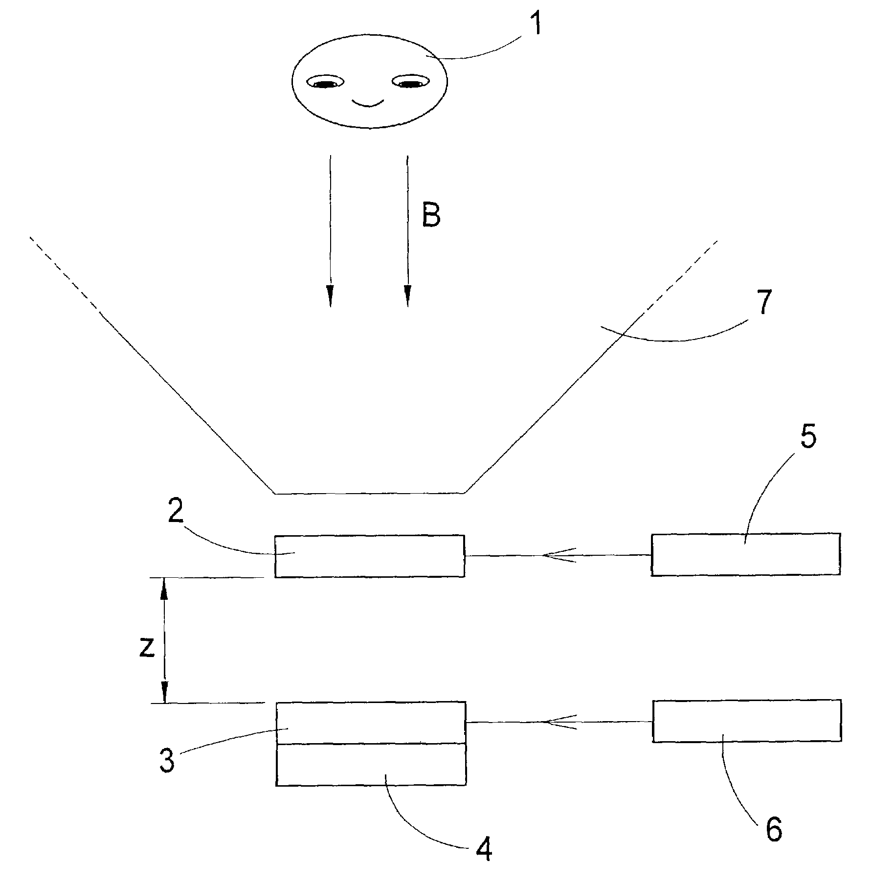
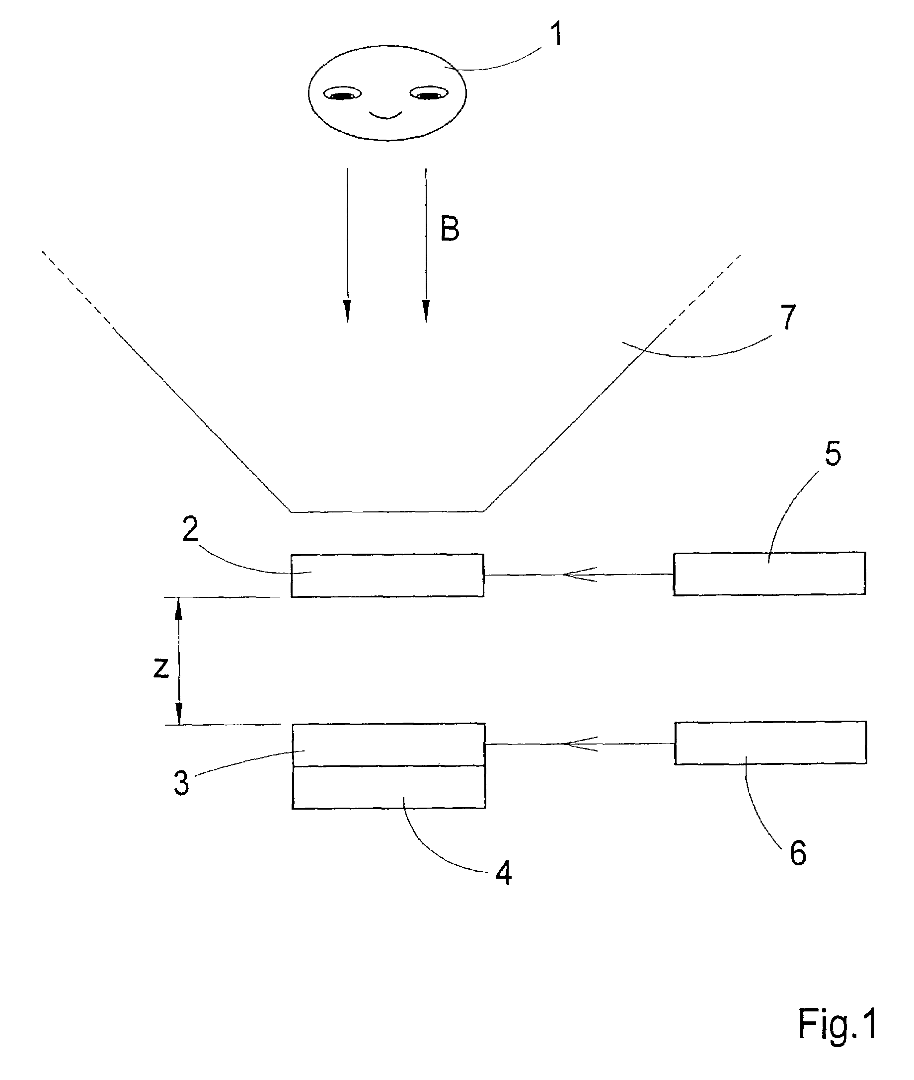
[0018]Proceeding from the prior art mentioned above, it is the object of the invention to achieve an autostereoscopic display for a plurality of observers simultaneously with a few, preferably commercially available, optical components while improving perceptibility.

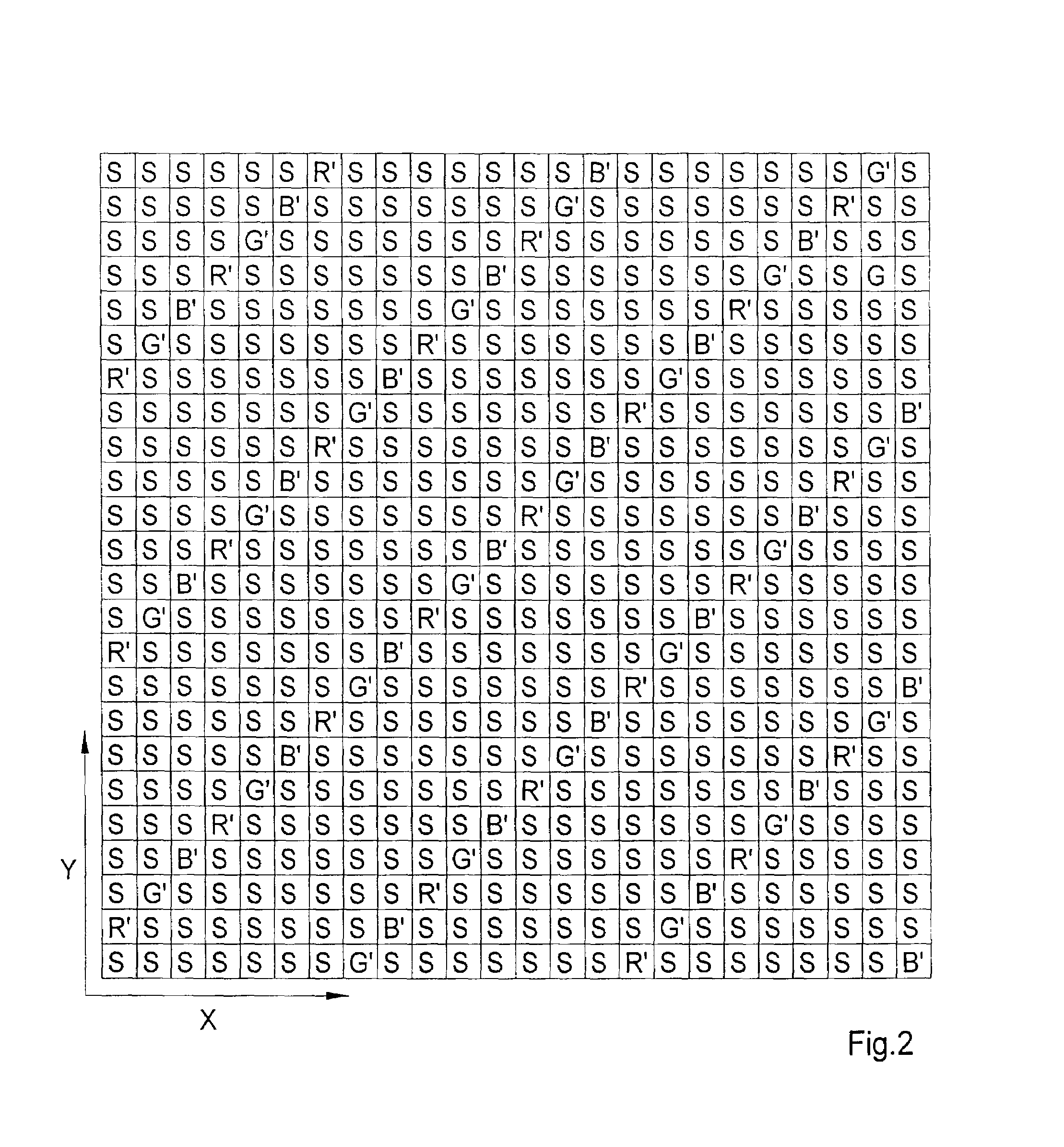
[0019]According to the invention, in a method of the type described above, propagation directions are predetermined for the light radiated from the image elements αij, which propagation directions depend on the wavelength of this light, wherein the propagation directions within an observation space in which the observer or observers is or are situated intersect in a plurality of intersection points, each of which corresponds to an observation position. From each observation position, one eye of an observer perceives predominantly image elements αij of a first selection and the other eye perceives predominantly image elements αij of a second selection from views Ak (k=1 . . . n).

[0020]In this connection, an image element ...


PUM


Abstract

A method for three-dimensional display in which a plurality of individual image elements αij are made visible simultaneously in a raster of columns i and lines j, wherein the image elements αij reproduce partial information from a plurality of views Ak (k1 . . . n) of a scene / object, and adjacent image elements αij radiate light of different wavelengths or wavelength regions is provided. In a method of the type described above, wavelength-dependent propagation directions are predetermined for the light radiated from the image elements αij. The propagation directions within an observation space in which an observer is situated intersect in a plurality of intersection points which correspond to observation positions. From each observation position, one eye of an observer perceives predominantly partial information of a first selection and the other eye perceives predominantly partial information of a second selection from views Ak (k=1 . . . n).

Description

FIELD OF THE INVENTION[0001]The invention is directed to a method for three-dimensional display of a scene / object in which a plurality of individual image elements αij are made visible simultaneously in a grid or raster of columns i and lines j, wherein the image elements αij reproduce partial information from a plurality of views Ak (k-1 . . . n) of the scene / object, and wherein adjacent image elements αij radiate light of different wavelengths Δ or wavelength regions Δλ. The invention is further directed to arrangements for carrying out the method.PRIOR ART[0002]As a result of the efforts made to display objects, landscapes, interior views of bodies and other things based on imaging so that they are perceivable three-dimensionally by the observer, a large number of autostereoscopic methods have arisen in the course of development which can be roughly distinguished as lenticular methods, prism raster methods and barrier methods.[0003]These methods are based on the principle of opti...

Claims


Application Information

Patent Timeline
Patent Type & Authority Patents(United States)
IPC IPC(8): H04N13/04F21V8/00H04N13/32G02B6/00G02B27/22
CPCG02B6/0043G02B6/0061G02B27/22G02B27/2214G02B27/225H04N13/0409H04N13/0422H04N13/0447G02B27/2271G02B6/0051H04N13/0497H04N13/0404H04N13/0456H04N13/047H04N13/305H04N13/324H04N13/368H04N13/31H04N13/361H04N13/398H04N13/351H04N13/30G02B30/50H04N13/32G02B30/27
Inventor DOERFEL, FALKGRASNICK, ARMINHOLZ, ANDREASKLIPPSTEIN, MARKUSRELKE, INGOSCHERZBERG-NAUJOKAT, SVEN-MARTINTZSCHOPPE, WOLFGANGURTECHO VALVERDE, RUDYARD ISAAC
Owner PHOENIX 3D INC
Why Eureka
Try Eureka