Transmissive liquid crystal display device

a liquid crystal display device and liquid crystal display technology, applied in the direction of instruments, static indicating devices, etc., can solve the problems of large power consumption of backlight, low use efficiency of backlight light, and inability to reduce the absorption of light by color filters, etc., to achieve the effect of reducing the overall backlight power consumption and optimizing the backlight valu

Inactive Publication Date: 2009-04-02
SHARP KK
View PDF13 Cites 42 Cited by
  • Summary
  • Abstract
  • Description
  • Claims
  • Application Information

AI Technical Summary

Benefits of technology

[0022]According to the configuration, the multiple backlights enable an optimal backlight value to be deter

Problems solved by technology

That results in a low use efficiency for the light emitted by the backlight, which in turn leads to a problem of large p

Method used


Image

  • Transmissive liquid crystal display device
  • Transmissive liquid crystal display device
  • Transmissive liquid crystal display device

Examples


embodiment 1

[0080]FIG. 6 illustrates the configuration of the luminance lowering section 12 in a liquid crystal display device of present embodiment 1. The luminance lowering section 12 includes a luminance-lowering maximum backlight value calculation section 21 and a luminance-lowered RGB signal calculation section 22. FIG. 7 is a flow chart of the operation of the luminance lowering section 12.

[0081]First, the luminance-lowering maximum backlight value calculation section 21 calculates a maximum backlight value MAXwy by equation (1) below (S11). Equation (1) will be derived later.

MAXwy=MAX×B1Ratioy  (1)

where MAX is a maximum value of the input RGB signals (i.e., the maximum one of the backlight values when neither chroma lowering nor luminance lowering is preformed) and B1Ratioy is a luminance-lowering backlight value setup ratio (0≦B1Ratioy≦1).

[0082]The luminance lowering section 12 carries out the luminance lowering processing on high luminance pixels. In other words, no luminance lowering ...

embodiment 2

[0137]Embodiment 1 above lowered the backlight value by lowering only luminance. Present embodiment 2 lowers the backlight value by lowering both chroma and luminance.

[0138]Lowering only luminance by very large amounts as in embodiment 1 makes degradation of image quality easy to recognize. Lowering both luminance and chroma by moderate amounts lowers the backlight value similarly to lowering only luminance, while not making degradation of image quality as easy to recognize. The same members as in embodiment 1 are given the same reference numerals as in embodiment 1, and their detailed description is not repeated here.

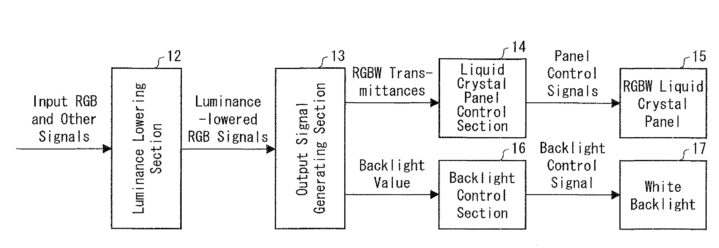
[0139]The liquid crystal display device of present embodiment 2, as illustrated in FIG. 10, includes a chroma lowering section 11, a luminance lowering section 12, an output signal generating section 13, a liquid crystal panel control section 14, an RGBW liquid crystal panel (“liquid crystal panel”) 15, a backlight control section 16, and a white backlight (“backlight”...


PUM


Abstract

In a transmissive liquid crystal display device including a liquid crystal panel and a backlight, the liquid crystal panel contains pixels each divided into four subpixels, a red (R), a green (G), a blue (B), and a white (W) subpixel. The backlight is a white backlight emitting light with controllable emission luminance. A luminance lowering section performs luminance lowering processing on input RGB signals (original input signals) for transformation into luminance-lowered RGB signals. An output signal generating section obtains transmittances and a backlight value from the luminance-lowered RGB signals.

Description

[0001]This nonprovisional application claims priority under 35 U.S.C. § 119(a) on Patent Application No. 2007-252701 filed in Japan on Sep. 27, 2007, the entire contents of which are hereby incorporated by reference.FIELD OF THE INVENTION[0002]The present invention relates to transmissive liquid crystal display devices constructed of a backlight and a liquid crystal panel.BACKGROUND OF THE INVENTION[0003]There exist various types of color display devices are available for commercial use. Thin-type display devices are divided into two main categories: self-luminous types like the PDP (plasma display panel) and non-luminous types like the LCD (liquid crystal display). A well-known subcategory of the LCD, a typical example of non-luminous type display devices, is the transmissive LCD containing a backlight behind a liquid crystal panel.[0004]FIG. 16 is a cross-sectional view of a general structure of the transmissive LCD. The transmissive LCD includes a backlight 110 behind a liquid cr...

Claims


Application Information

Patent Timeline
IPC IPC(8): G09G3/36
CPCG09G3/3406G09G3/342G09G3/3607G09G3/3611G09G2360/16G09G2320/0646G09G2320/0666G09G2330/021G09G2340/06G09G2300/0452
Inventor MORISUE, TAKASHIMURAMATSU, TSUYOSHIAOKI, ATSUSHITANAKA, HIROSHI
Owner SHARP KK
Why Eureka
Try Eureka