Blade driving device for use in cameras

a driving device and camera technology, applied in the direction of camera diaphragms, shutters, instruments, etc., can solve the problem that fastening parts such as screws become unnecessary, and achieve the effect of smooth movemen

Inactive Publication Date: 2007-01-02
COPAL CO LTD
View PDF6 Cites 38 Cited by
  • Summary
  • Abstract
  • Description
  • Claims
  • Application Information

AI Technical Summary

Benefits of technology

[0006]The present invention has been made in consideration of the abovementioned problems in the conventional art, and an object thereof is to provide a blade driving device for use in cameras which employs an electromagnetic actuator which is capable of simplifying the manufacturing process and the structure by reducing the number of components to as small as possible, and drives a shutter blade, a diaphragm blade, or an ND filter blade, etc., by the electromagnetic actuator in, in particular, small-sized digital cameras.
[0007]The blade driving device for use in cameras of the present invention achieving the abovementioned object includes a base plate having an exposure aperture, a blade member which is rotatably supported by a supporting shaft on the base plate and is movable to a position withdrawn from the exposure aperture and a position facing the exposure aperture, and an electromagnetic actuator that drives the blade member. The electromagnetic actuator includes a frame member to be joined to the base plate, a rotor which has a drive pin that exerts a driving force to the blade member and rotates within a predetermined angle range with one end of the rotor being supported by the frame member and the other end of the rotor being supported by the base plate, and an exciting coil wound around the frame member and the base plate. The blade member is a shutter blade that opens and closes the exposure aperture, a diaphragm blade that stops down the exposure aperture to a predetermined diameter, or an ND filter blade that reduces the amount of light by covering the exposure aperture.
[0008]According to this structure, the rotor is supported in a rotatable manner by the frame member and the base plate and the coil is wound around the frame member and the base plate, so that the electromagnetic actuator can be assembled simultaneously with the step of attaching various parts to the substrate. Namely, in comparison with the conventional art, only one frame member is used, and the coil is wound around the frame member and the base plate while sandwiching and holding the rotor in a rotatable manner, so that fastening parts such as screws become unnecessary. Therefore, the number of parts can be reduced and a simplified structure and low cost are realized, and in addition, the structure of the electromagnetic actuator is simplified and reduced in height, whereby the device can be reduced in size and thickness.

Problems solved by technology

Namely, in comparison with the conventional art, only one frame member is used, and the coil is wound around the frame member and the base plate while sandwiching and holding the rotor in a rotatable manner, so that fastening parts such as screws become unnecessary.

Method used


Image

  • Blade driving device for use in cameras
  • Blade driving device for use in cameras
  • Blade driving device for use in cameras

Examples


Embodiment Construction

[0045]Hereinafter, preferred embodiments of the present invention are described with reference to the accompanying drawings.

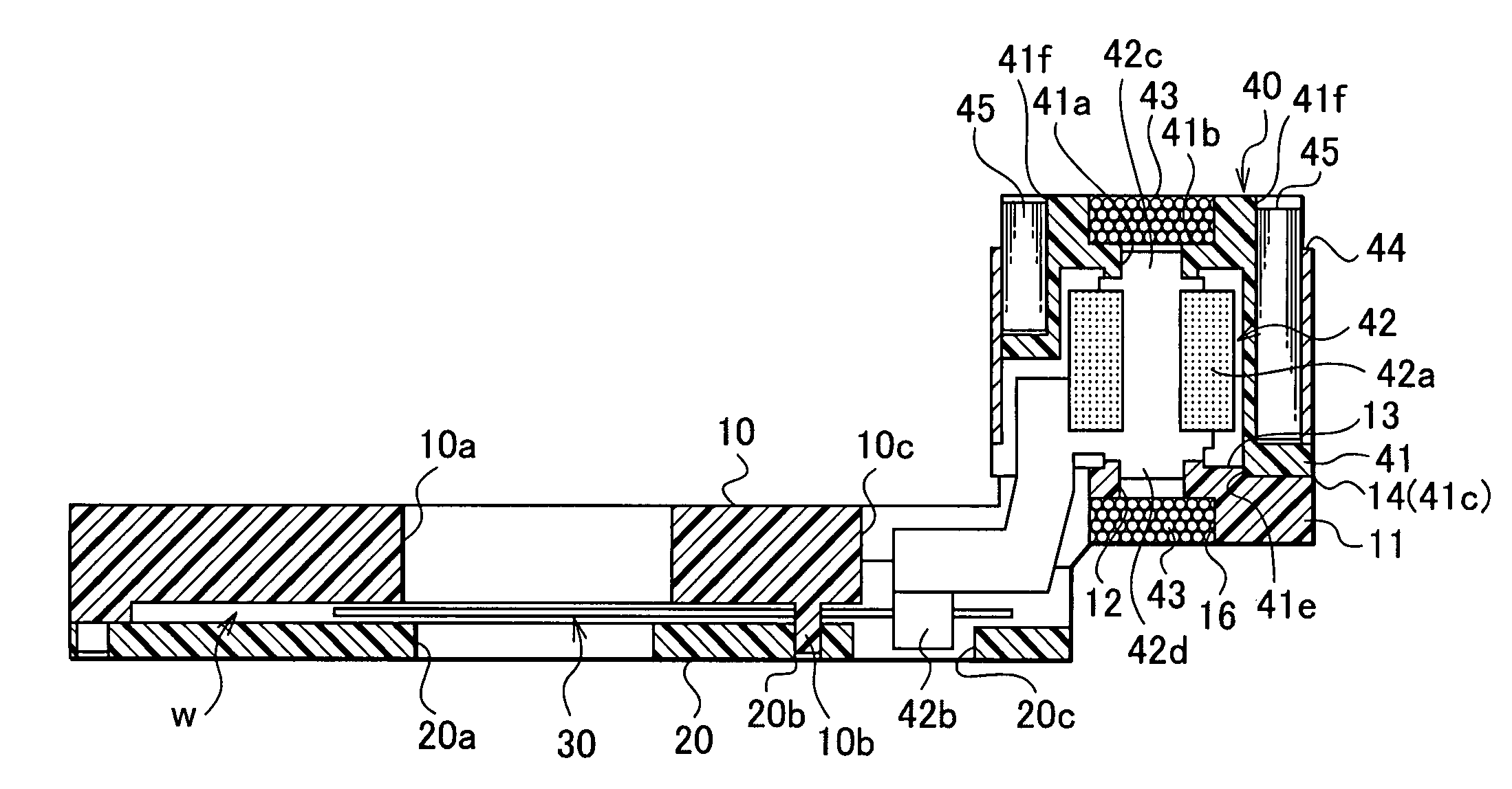
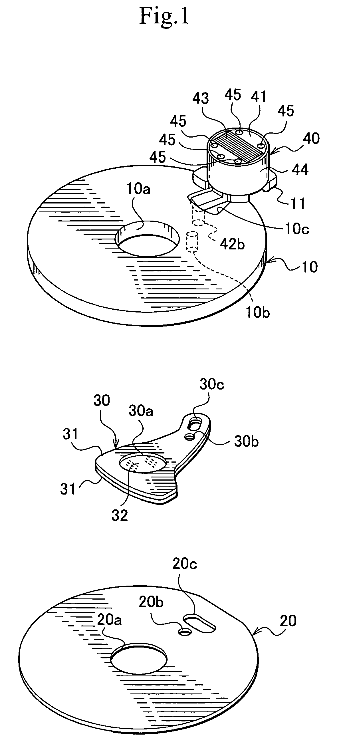
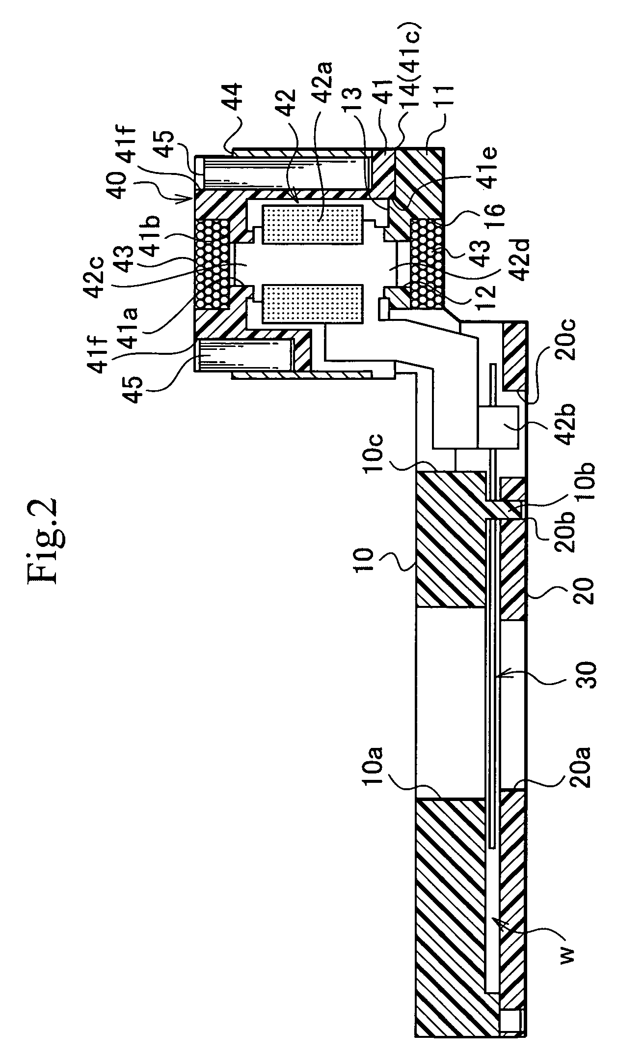
[0046]A light amount adjusting device as an embodiment of a blade driving device for use in cameras of the present invention includes, as shown in FIG. 1 and FIG. 2, a main plate 10 and a back plate 20 as a base plate that have exposure apertures 10a and 20a, an ND filter blade 30 as a blade member that is supported to be rotatable around a supporting shaft 10b on the main plate 10 and moves to a position facing the exposure apertures 10a and 20a and a position withdrawn from the exposure apertures 10a and 20a, and an electromagnetic actuator 40 that drives the ND filter blade 30, and so on.

[0047]As shown in FIG. 1, FIG. 2, FIG. 4, and FIG. 5, the main plate 10 is roughly formed into a disk shape, and on a part of its outline form, a plate-shaped projection 11 that projects outward in the diameter direction with respect to the exposure aperture 10a is integrall...


PUM


Abstract

A blade driving device for use in cameras of the present invention includes a base plate having an exposure aperture, an ND filter blade that is supported rotatably around a supporting shaft on the base plate and is moved to a position withdrawn from the exposure aperture and a position facing the exposure aperture, and an electromagnetic actuator that drives the ND filter blade. This electromagnetic actuator includes a frame member joined to the base plate, a rotor which has a drive pin for exerting a driving force and rotates within a predetermined angle range with one end of which being supported to the frame member and the other end of which being supported to the base plate, and an exciting coil wound around the frame member and the base plate. Therefore, the structure of the electromagnetic actuator for driving a shutter blade, a diaphragm blade, an ND filter blade or the like can be simplified and reduced in cost, and this makes it possible to reduce the size and thickness of the device.

Description

BACKGROUND OF THE INVENTION[0001]1. Field of the Invention[0002]The present invention relates to a blade driving device for use in cameras which is installed in a camera, etc., and drives a blade that opens and closes an exposure aperture or a blade that reduces the amount of light to pass through the exposure aperture, and more particularly, a blade driving device for use in cameras which comprises an electromagnetic actuator including a rotor for driving the blade.[0003]2. Description of the Related Art[0004]As a conventional blade driving device for use in cameras, for example, there is known a blade driving device for use in cameras which drives a shutter blade or a diaphragm blade by joining an electromagnetic actuator, formed of an upper frame member and a lower frame member that are joined to each other and rotatably support a rotor, an exciting coil wound around the upper frame member and the lower frame member, and a cylindrical yoke or the like attached to the upper frame ...

Claims


Application Information

Patent Timeline
Patent Type & Authority Patents(United States)
IPC IPC(8): G03B9/08G03B9/02G03B9/10G03B9/26
CPCG03B9/08
Inventor WATANABE, NOBUAKIYAMAGISHI, SHIGERUEGURO, TOHRU
Owner COPAL CO LTD
Why Eureka
Try Eureka