
Endoscope apparatus and control method therefor

a technology of endoscope and endoscope body, which is applied in the field of endoscope apparatus, can solve the problems of insufficient light emitted to the living tissue, insufficient image, and significant disadvantage, and achieve the effect of better timing

Inactive Publication Date: 2010-04-22
FUJIFILM CORP
View PDF11 Cites 42 Cited by
  • Summary
  • Abstract
  • Description
  • Claims
  • Application Information

AI Technical Summary

Benefits of technology

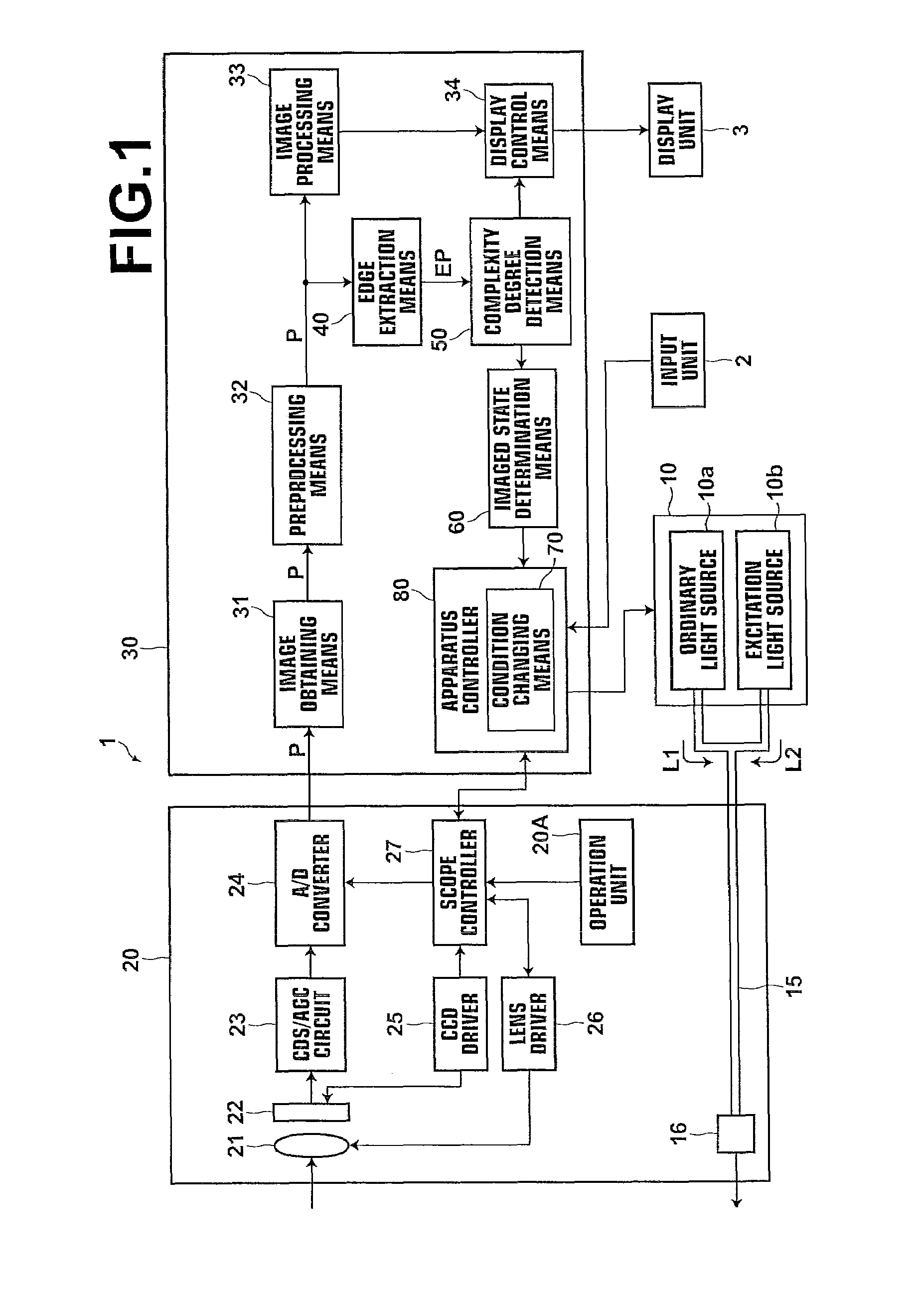
[0031]Further, the scope may be a scope having a light emitting means for emitting light to the subject, and the condition changing means may be a means that decreases the amount of the light emitted from the light emitting means for the near view imaging and increases the amount of the light emitted from the light emitting means for the distant view imaging.
[0064]Still further, if a notification that the apparatus is set to the switchable state is made, the operator may know that the apparatus becomes switchable, so that switching between obtaining of the estimated spectral image signal and obtaining of the narrowband image signal may be made at a better timing.

Problems solved by technology

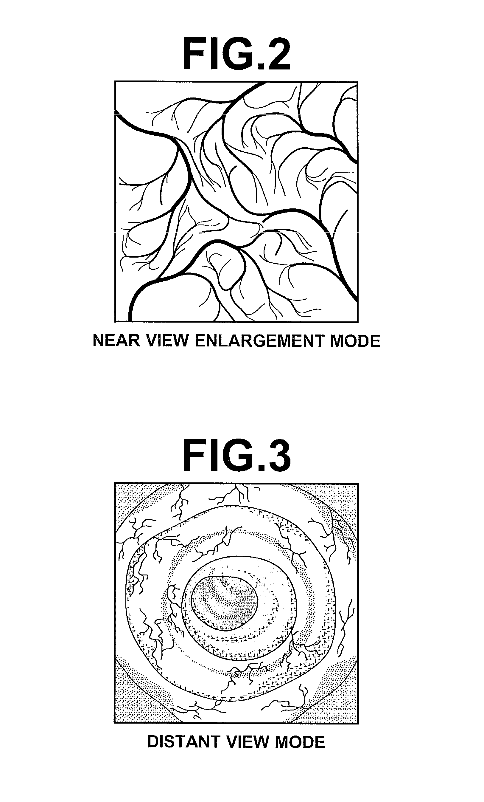
The narrowband image obtained by the apparatus described in Japanese Unexamined Patent Publication No. 2002-095635, however, is an image obtained by emitting light transmitted through the narrowband filter, thus causing a disadvantage that the amount of light emitted to a living tissue is insufficient and the image becomes dark.
This disadvantage particularly becomes significant when a distant view image is obtained.
In the mean time, the spectrally estimated image obtained by the apparatus described in Japanese Unexamined Patent Publication No. 2003-093336 has sufficient brightness, but the wavelength estimation by the matrix operation has limitations on the accuracy, whereby the image quality may be degraded compared to the narrowband image.
This disadvantage becomes more significant when a near view enlarged image is obtained.

Method used


Image

  • Endoscope apparatus and control method therefor
  • Endoscope apparatus and control method therefor
  • Endoscope apparatus and control method therefor

Examples


Embodiment Construction

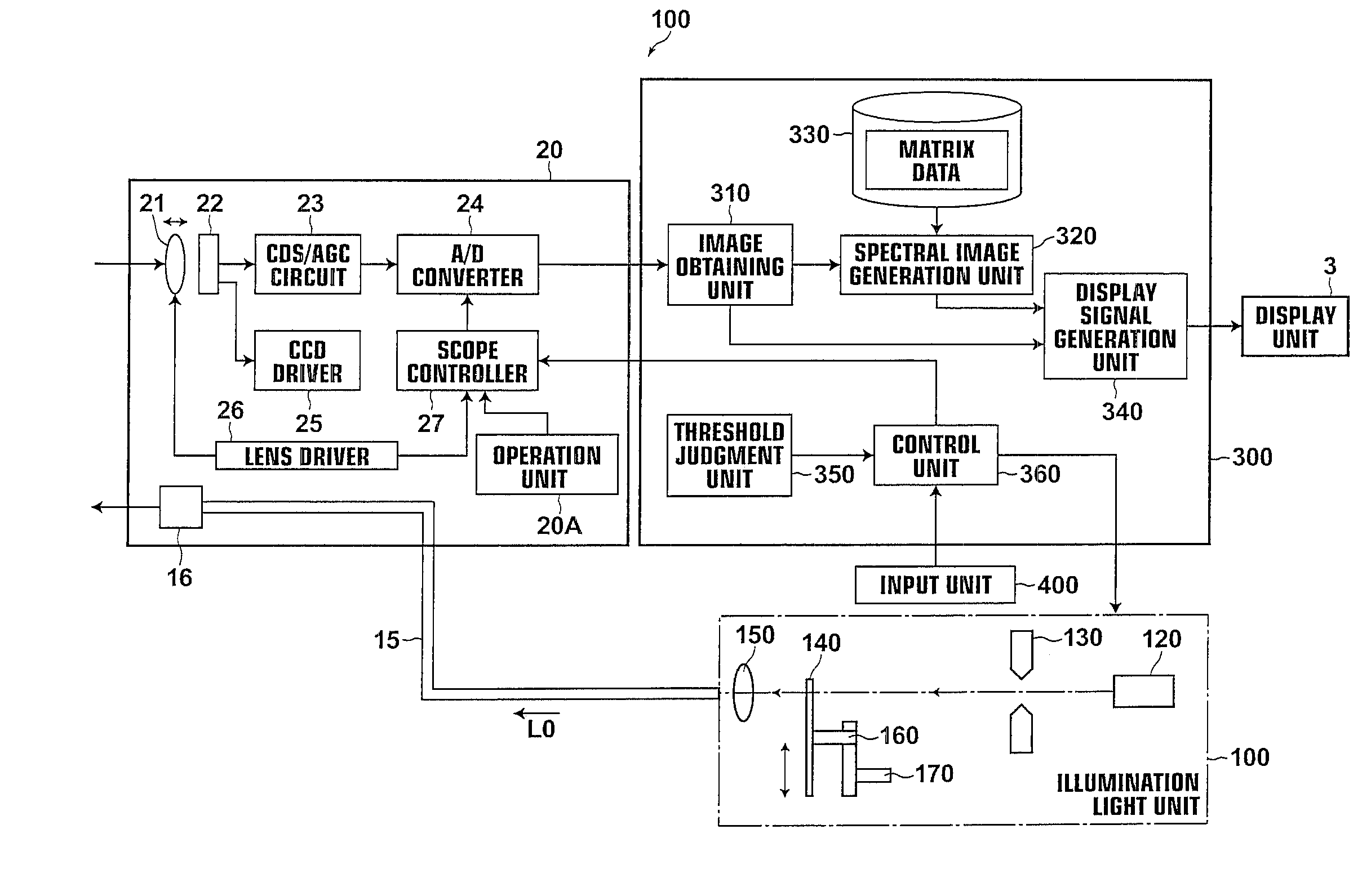
[0075]Hereinafter, a first embodiment of the present invention will be described in detail with reference to the accompanying drawings. FIG. 1 is a block diagram of an example of endoscope apparatus incorporating a first embodiment of the present invention. Endoscope apparatus 1 includes light source unit 10, scope 20, and image processing unit 30. Light source unit 10 is a unit for emitting light to a subject when observing the subject by the endoscope apparatus. Light source unit 10 includes ordinary light source 10a, such as a xenon lamp or the like, for an ordinary observation and excitation light source 10b for a fluorescence observation, the operation of which is controlled by apparatus controller 80. Ordinary light source 10a emits white light and excitation light source 10b emits excitation light as described above, the wavelength of which is, for example, 682 nm or 747 nm. Light source unit 10 is optically linked to light guide 15 of scope 20, and white light L1 or excitati...


PUM


Abstract

An endoscope image is obtained by imaging a subject with a scope. Then, an edge portion of the endoscope image is extracted and a complexity degree of the edge portion is detected. Thereafter, a determination is made as to whether the endoscope image is an image obtained through near view imaging or distant view imaging according to the complexity degree and an imaging condition is changed according to the determined near view imaging or distant view imaging.

Description

BACKGROUND OF THE INVENTION[0001]1. Field of the Invention[0002]The present invention relates to an endoscope apparatus capable of controlling various imaging modes and a control method therefor.[0003]2. Description of the Related Art[0004]Endoscope apparatuses for obtaining an image of a body cavity, such as esophagus, stomach, large intestine, and the like, by inserting a scope inside of the body cavity are used in order to perform image diagnosis for the state of the body cavity. Recently, when performing image diagnosis through the endoscope, it has become possible that an endoscope image obtained by the scope is displayed on a monitor in real time and the doctor is able to perform image diagnosis while confirming the imaged area with the monitor.[0005]In order to facilitate image diagnosis, various observation modes using the endoscope are available, including ordinary observation mode in which a subject illuminated with white light is observed, fluorescence observation mode in...

Claims


Application Information

Patent Timeline
Patent Type & Authority Applications(United States)
IPC IPC(8): H04N7/18A61B1/045
CPCA61B1/00188A61B1/0646G06T7/0012G06T7/0085G06T7/406G06T2207/10068G06T2207/10152G06T2207/30028G06T2207/30092H04N5/232H04N5/23245H04N2005/2255H04N2209/044A61B1/063A61B1/0638G06T7/13G06T7/48A61B1/0655H04N23/555H04N23/667H04N23/63
Inventor KUBO, MASAHIROOHTA, YASUNORITAKAHIRA, MASAYUKIKINJO, NAOTO
Owner FUJIFILM CORP
Learn More