Cooperative position location via wireless data link using broadcast digital transmissions

a wireless data link and wireless data technology, applied in the field of radio geolocation, can solve the problems of different clock bias and drift of the timing source at the bdt transmitter, and achieve the effects of convenient adjustment, improved timing, and easy adjustment of broadcast signal characteristics

Inactive Publication Date: 2011-11-22
YANG CHUN
View PDF15 Cites 58 Cited by
  • Summary
  • Abstract
  • Description
  • Claims
  • Application Information

AI Technical Summary

Benefits of technology

[0017]In a particular embodiment, the broadcast digital transmission (BDT) is a broadcast digital television (DTV) signal and the broadcast digital television signal is an Advanced Television Systems Committee (ATSC) digital television signal. The special periodic code is a field synchronization segment with an ATSC / DTV data frame, a segment synchronization sequence within a data segment within an ATSC / DTV data frame, or a combination thereof. In addition, an ATSC DTV signal may also contain a pseudorandom sequence as a “RF watermark” that is uniquely assigned to each DTV transmitter for transmitter identification (TxID) in system monitoring and measurement, which can also serve as the special periodic code. However, different from GPS signals, general broadcast digital transmissions do not contain timing information directly. In addition, as signals of opportunity, BDT signals are typically not synchronized (in contrast to GPS wherein all satellites operate on the well-maintained GPS time). Besides, the timing source at BDT transmitters is subject to different clock bias and drift (whereas atomic clocks onboard GPS satellites are constantly calibrated by ground stations). These are inherent technical difficulties in using signals of opportunity by a standalone device to derive position location information. In the present invention, times of arrival (TOA) of the special codes measured at individual CPLDs are communicated to one another via data link transceivers to form a time difference of arrival (TDOA) so as to eliminate the clock errors of BDT transmitters.
[0021]When a BDT receiver is implemented as a software receiver, any change in broadcast signal characteristics can be easily accommodated by simply reprogramming the receiver when moving from one region or one country to another. Similarly, when a data link transceiver is implemented as a software receiver, any change in ranging protocols and signaling waveforms can be easily accommodated by simply reprogramming the transceiver. When a different displacement sensor (or other auxiliary sensors for the matter) is used, it suffices to modify sensor error models in the joint calibration and positioning solution by reprogramming. In an urban environment, the direct signal from a transmitter may be attenuated whereas the multipath signals reflected from surroundings, although arriving later in time, may appear stronger. When moving from an environment to another, the cooperative position location device can be programmed to use a channel impulse response or a generalized frequency-domain correlator (GFDC) instead of a conventional delay-lock loop (DLL). As a preferred method, the use of a channel impulse response or a GFDC in the present invention produces a major portion of the correlation function (or the entire function if desired) from which the direct signal and multipath fingerprint can be isolated. And more importantly, the impulse response or the generalized correlation peak is much sharper, thus being less susceptible to multipath and leading to better timing and ultimately to better position location.

Problems solved by technology

However, different from GPS signals, general broadcast digital transmissions do not contain timing information directly.
In addition, as signals of opportunity, BDT signals are typically not synchronized (in contrast to GPS wherein all satellites operate on the well-maintained GPS time).
Besides, the timing source at BDT transmitters is subject to different clock bias and drift (whereas atomic clocks onboard GPS satellites are constantly calibrated by ground stations).
These are inherent technical difficulties in using signals of opportunity by a standalone device to derive position location information.

Method used


Image

  • Cooperative position location via wireless data link using broadcast digital transmissions
  • Cooperative position location via wireless data link using broadcast digital transmissions
  • Cooperative position location via wireless data link using broadcast digital transmissions

Examples


embodiment 100

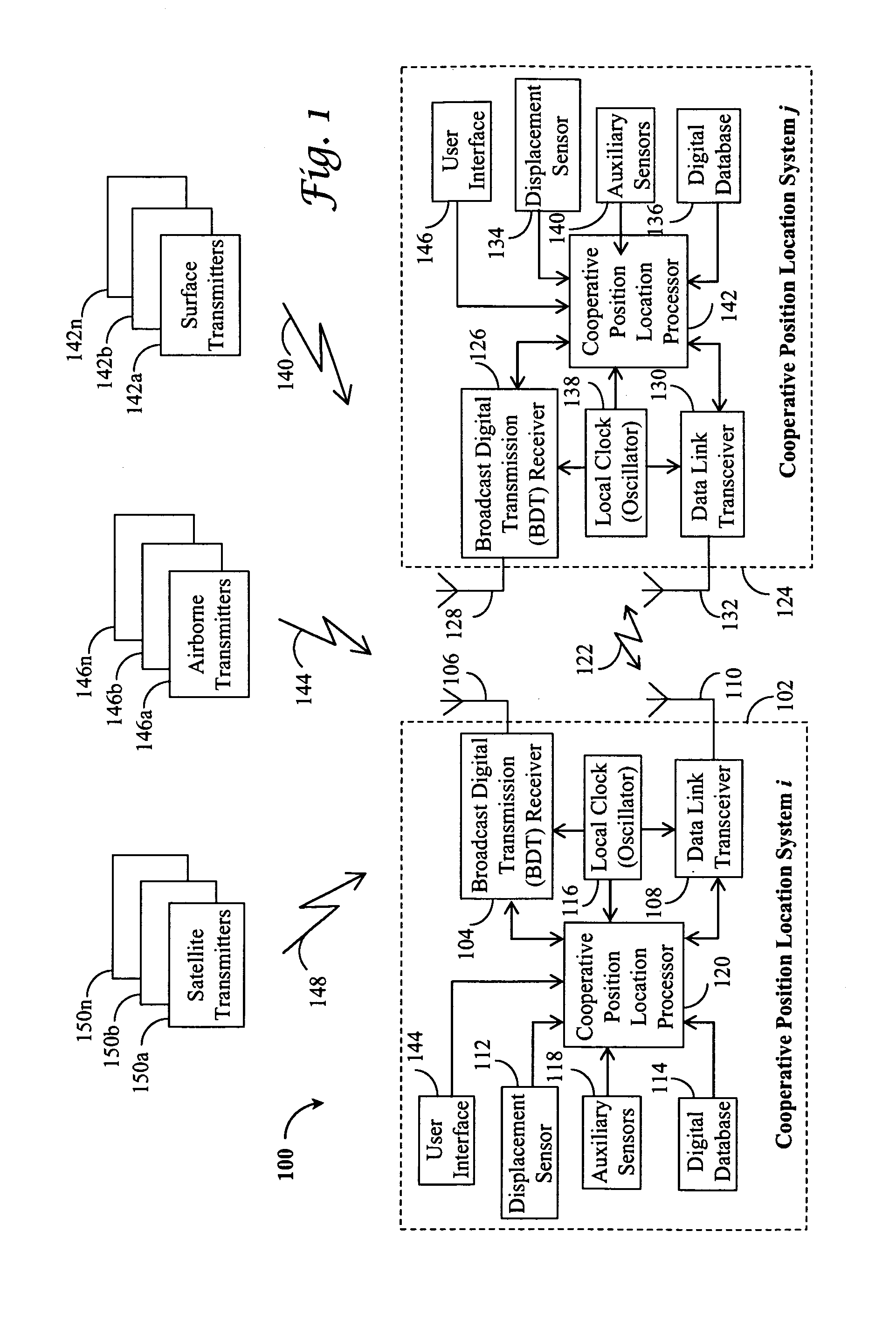
[0034]Referring to FIG. 1, an exemplar embodiment 100 of the present invention is sketched wherein two cooperative position location systems i 102 and j 124, respectively, are present. Broadcast digital transmissions 140, 144, and 148 from a plurality of transmitters are received by broadcast digital transmission (BDT) receivers 104 and 126 via antennas 106 and 128, respectively. This may include surface transmitters 142a and 142b through 142n at known locations on the ground for instances. It may also include airborne transmitters 146a and 146b through 146n with their locations either embedded in digital transmissions or made available to cooperative position location systems 102 and 124 by other means. Satellite transmitters 150a and 150b through 150n can also be used in a similar manner. In a sense, GPS satellites fall into this category because a GPS satellite broadcasts its orbit and clock information within navigation messages modulated on the radio signal. More generally, sur...

exemplary embodiment 200

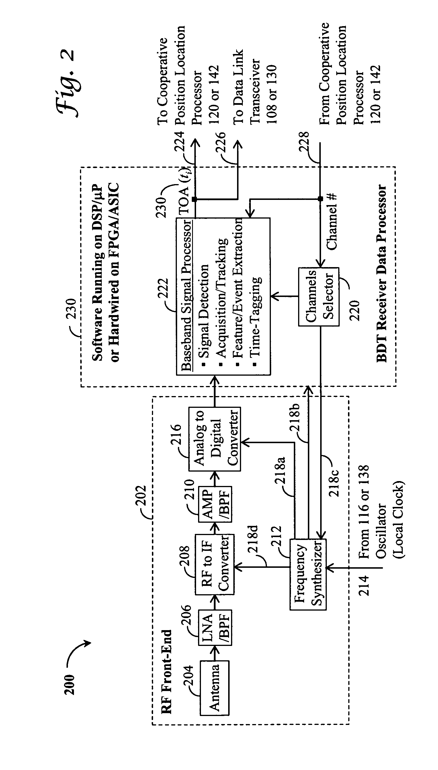
[0037]Referring to FIG. 2, an exemplary embodiment 200 of a broadcast digital transmission (BDT) receiver 104 or 126 is depicted with a radio frequency (RF) front-end 202 coupled to a BDT receiver data processor 230 with software running either on a digital signal processor (DSP) / a microprocessor (μP) or hardwired on a field programmable gate array (FPGA) / an application-specific integrated circuit (ASIC) chip in accordance with the present invention. More specifically, an antenna 204 intercepts RF signals that come from a plurality of transmitters on the ground 140, in the air 144, and / or from the space 148. Captured signals are low-noise amplified (LNA) and bandpass-filtered (BPF) 206 and coupled to a RF to IF converter 208 with mixers. There may be several RF to IF down-conversion stages, each followed by an amplifier (AMP) / a bandpass filter (BPF) 210 in order to reach the desired gain and bandwidth while minimizing unwanted nonlinearity and interference effects. To drive the RF f...

exemplary embodiment 400

[0048]Referring to FIG. 4, an exemplary embodiment 400 of a data link transceiver 108 or 130 is depicted with a data receive channel 402, a data transmit channel 420, and a data link transceiver data processor 440 in accordance with the present invention. The data receive channel 402 comprises an antenna 404, a low-noise amplifier (LNA) and a bandpass-filter (BPF) 406, several RF to IF down-conversion stages 408, each followed by an amplifier (AMP) / a bandpass filter (BPF) 410, and an analog to digital converter (ADC) 412. On the other hand, the data transmit channel 420 consists of a data modulator 430, several IF to RF up-conversion stages 426, each preceded by an amplifier (AMP) / a bandpass filter (BPF) 428, a power amplifier 424, and an antenna 422. To drive the data receive channel 402 and data transmit channel 422, various frequency components 418a and 418b are produced by a frequency synthesizer 416 driven in turn by a crystal oscillator 414 (from 116 or 138). The frequency syn...


PUM


Abstract

A cooperative position location device (CPLD) that integrates a broadcast digital transmission (BDT) receiver, a data link transceiver, and a displacement sensor; a computer program product tangibly stored in computer-readable media; and associated methods for receiving and processing special codes embedded in BDT signals from a plurality of transmitters to produce time of arrival (TOA) measurements thereof; for sending and receiving special messages between cooperative position location devices (CPLDs) to produce time difference of arrival (TDOA) of common events of BDT at and time of flight (TOF) measurements between the CPLDs; and for integrating differential and relative ranges between CPLDs to a plurality of BDT transmitters and displacement measurements to yield a joint position solution of the CPLDs.

Description

BACKGROUND OF THE INVENTION[0001]1. Field of the Invention[0002]The present invention relates generally to radio geolocation and particularly to cooperative receivers for position location using periodic codes in such broadcast digital transmissions as broadcast digital television (DTV) and wireless local area network (WLAN) signals.[0003]2. Description of the Prior Art[0004]Among different radio geolocation and navigation systems, there are two important systems in wide use today. One is the 100 kHz Long Range Navigation-C (LORAN-C) system which evolved to the present form in the mid-1950s. It uses terrestrial radio transmitters to provide navigation, location, and timing services for suitably equipped air, land and marine users, civil and military alike. A LORAN-C receiver measures the difference in times of arrival of pulses transmitted by a chain of three to six synchronized transmitter stations separated by hundreds of kilometers. There are many LORAN chains of stations around ...

Claims


Application Information

Patent Timeline
Patent Type & Authority Patents(United States)
IPC IPC(8): G01S3/02
CPCG01S5/0072G01S5/009G01S5/0242G01S5/14
Inventor YANG, CHUN
Owner YANG CHUN
Why Eureka
Try Eureka