
Clock-error estimation for two-clock electronic device

A clock error, clock technology, applied in the field of operating dual clock electronic equipment

Pending Publication Date: 2021-09-03
贝斯普恩公司
View PDF0 Cites 0 Cited by
  • Summary
  • Abstract
  • Description
  • Claims
  • Application Information

AI Technical Summary

Problems solved by technology

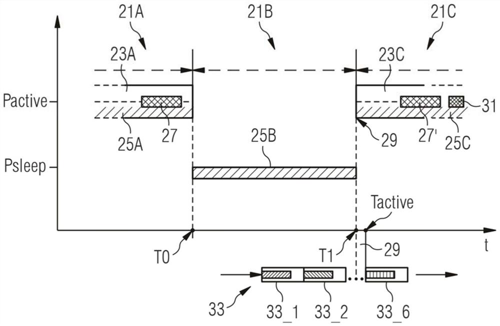
However, during some time intervals, those systems can only use low-power clocks to save power

Method used


Image

  • Clock-error estimation for two-clock electronic device
  • Clock-error estimation for two-clock electronic device
  • Clock-error estimation for two-clock electronic device

Examples


Embodiment Construction

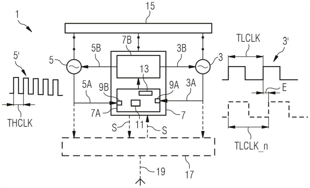
[0077] The following is a detailed description of exemplary embodiments of the present disclosure. The exemplary embodiments described herein and illustrated in the accompanying drawings are intended to teach the principles of the disclosure to enable one of ordinary skill in the art to implement and use the disclosure in many different environments and for many different applications. Therefore, the exemplary embodiments are not intended and should not be considered as a limiting description of the scope of patent protection.

[0078] Instead, the scope of patent protection shall be determined by the appended claims.

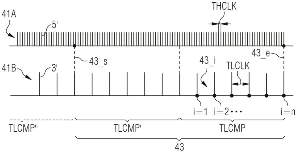
[0079] This disclosure is based in part on the realization that a particular measurement time period can improve the estimation of clock error. This improvement is achieved in particular by a specific clock counting process during the measurement time period. The inventors have particularly realized that the preferred measurement time period may be based on a...


PUM


Abstract

Clock-error estimation for a two-clock electronic device. An implementation method is used for deriving an estimation value of a clock-error for a slave clock, wherein the slave clock is set at a nominal slave period and outputs a sequence of slave clock signals at an actual slave period and wherein the difference between the actual slave period and the nominal slave period is approximated by the estimation value of the clock-error.

Description

[0001] Cross References to Related Applications [0002] This application claims the benefit of European Patent Application No. 20305147.9 filed February 17, 2020, which is hereby incorporated by reference. technical field [0003] The present disclosure relates generally to operating dual clock electronics and, in particular, to finding an estimate of a clock error of one of two clocks of a dual clock electronics. Furthermore, the present disclosure relates to implementing such clock error estimation into a positioning system, particularly an ultra-wideband (UWB) positioning system based on communicating UWB signals between mobile tag devices and stationary devices. For example, the present disclosure relates to efficiently controlling timing within such UWB communications, particularly with respect to the sequence of exchanging UWB signals within a UWB communications frame. Background technique [0004] For the concepts disclosed herein, an electronic device includes two...

Claims


Application Information

Patent Timeline
Patent Type & Authority Applications(China)
IPC IPC(8): H04W4/02H04W4/33H04W52/02G04G5/00
CPCH04W4/023H04W4/33H04W52/0248G04G5/00H04W56/0015G06F13/4291Y02D10/00G06F1/08G06F1/12G06F1/14G06F11/1679
Inventor P·法布雷
Owner 贝斯普恩公司
Learn More