Display drive control circuit

Active Publication Date: 2007-02-13
SYNAPTICS JAPAN GK
View PDF11 Cites 5 Cited by
  • Summary
  • Abstract
  • Description
  • Claims
  • Application Information

AI Technical Summary

Benefits of technology

[0003]Requirement for display of moving pictures on a display screen of a mobile telephone is increasing in recent years. However, since the existing mobile telephone has been mainly used to display still pictures including a text, a drive control circuit thereof is only provided with a still-picture

Problems solved by technology

Therefore, such interface is not preferable from the viewpoint of display quality.
As described previously, it

Method used


Image

  • Display drive control circuit
  • Display drive control circuit
  • Display drive control circuit

Examples


Embodiment Construction

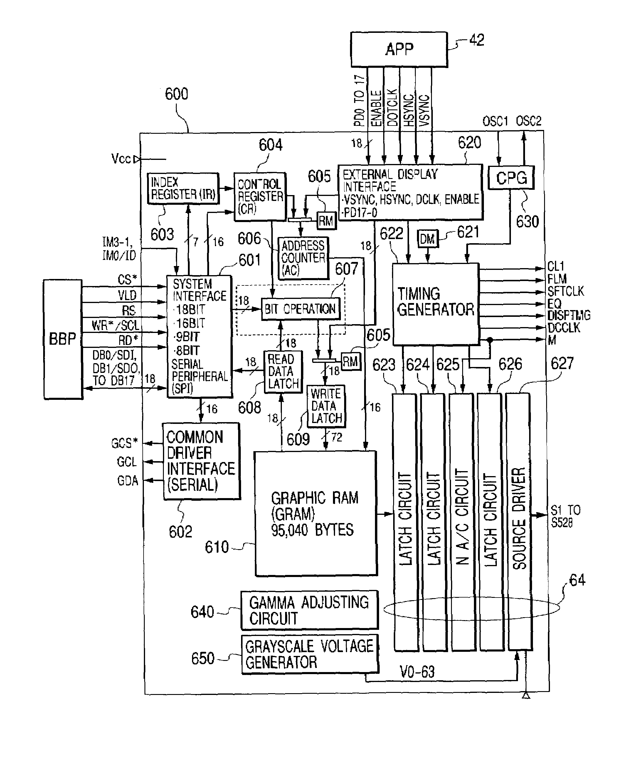
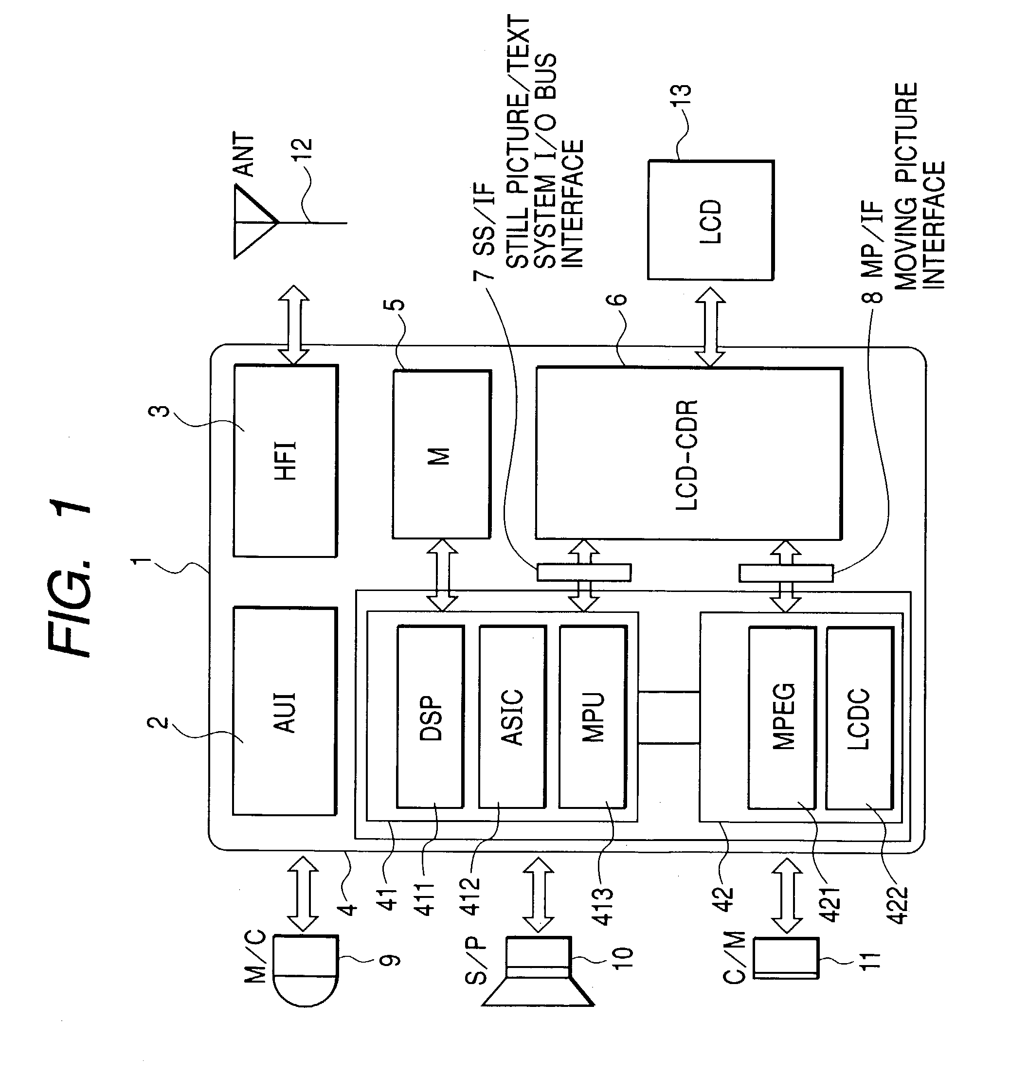
[0055]The preferred embodiments of the present invention will be described in detail with reference to the accompanying drawings thereof. FIG. 1 is a diagram for describing the entire configuration of an embodiment of the present invention and a block diagram for explaining an embodiment of a drive circuit system configuration of a mobile telephone including a moving picture interface (namely, including a first port to which moving picture data is transferred) referred to as a first function as an example of the display drive control circuit of the present invention. This display drive control circuit 1 is composed of an audio interface (AUI) 2 similar to that of FIG. 20, a high frequency interface (HFI) 3, a picture processor 4 as a picture data processor, a memory 5 as a picture display memory, a liquid crystal controller driver 6 (LCD-CDR) as a display drive control circuit, a still-picture·text·system·I / O bus·interface (SS / IF) 7 as a second function (namely, including a second p...


PUM


Abstract

No flicker is displayed on the display screen during display of moving pictures and power consumption can be reduced by adding a high quality moving picture display function. Moreover, the number of times of transfer of moving pictures by comprising a still-picture·text·system·I/O bus·interface and a moving picture interface (external display interface), providing a display operation change register (DM) and a RAM access change register (RM) which are changed selectively depending on display content (display mode) displayed on a display device and displaying the display data on the display device via a picture memory even in the moving picture display mode.

Description

BACKGROUND OF THE INVENTION[0001]The present invention relates to a display drive control technique for controlling a picture display mode of a display device and particularly to a display drive control circuit for controlling a picture display mode of a display device for displaying still pictures and moving pictures to a liquid crystal display device, an organic EL display device and other dot matrix type display device.[0002]In general, a dot matrix type display device is configured with a display panel including a large number of pixels arranged in a two-dimensional matrix and a display control circuit for displaying still pictures and moving pictures by supplying a picture signal to this display panel. As a display device of this type, a liquid crystal display device, an organic EL display device, a plasma display device or a field emission type display device, etc. are known. Summary of the picture display system is explained here considering, as an example thereof, a liquid c...

Claims


Application Information

Patent Timeline
IPC IPC(8): G09G3/36G02F1/133G09G3/20
CPCG09G3/3611G09G5/393G09G5/395G09G5/363G09G3/3685G09G5/12G09G2310/027G09G2320/0261G09G2320/103G09G2330/021G09G2340/125G09G2360/18G09G2320/0247G09G3/36
Inventor SAKAMAKI, GOROOHYAMA, TAKASHIOHTA, SHIGERUTANABE, KEI
Owner SYNAPTICS JAPAN GK
Why Eureka
Try Eureka