
Apparatus and method for determining beamforming vector in a codebook-based beamforming system

a beamforming system and codebook technology, applied in the field of codebook-based beamforming systems, can solve the problems of limited feedback reduction, inability to achieve transmission beamforming techniques, and drawbacks of conventional interpolation techniques concerning channel time-variant properties,

Inactive Publication Date: 2007-09-06
KOREA ADVANCED INST OF SCI & TECH +1
View PDF1 Cites 75 Cited by
  • Summary
  • Abstract
  • Description
  • Claims
  • Application Information

AI Technical Summary

Benefits of technology

[0026] Yet further object of the present invention is to provide an apparatus and method for improving transmission beamforming performance in a beamforming system.

Problems solved by technology

Yet, the transmission beamforming technique is viable only if the transmitter has knowledge of a transmission beamforming vector.
Although it is possible to decrease the feedback to some degree by limited feedback schemes proposed for the narrow-band MIMO system, the reduction of feedback is limited because of too large of a total number of subcarriers.
Despite its ability to reduce feedback for a broadband channel, the conventional interpolation technique has drawbacks concerning the time-variant properties of the channel.
Hence, the receiver has to continuously notify the transmitter of transmission beamforming vectors according to channel changes, requiring a large amount of feedback.
Moreover, if the system has a processing delay, that is, if the transmission beamforming vectors from the receiver cannot be used immediately due to some factors like detection delay at the transmitter, the channel may change during the processing delay.
As a consequence, even if the receiver optimizes the transmission beamforming vectors, they are not optimal at the transmitter any more.
Despite the codebook index-based feedback, this method requires a large amount of feedback.
This interpolation method requires a relatively high computational complexity in determining feedback information at the receiver, although decreasing the amount of feedback information.
Conventional techniques, however, have the problem of great performance degradation in a time-varying channel environment.
However, the channel variation becomes very serious just before the next feedback time instant.
What is worse, the performance degradation caused by the channel variation occurs every time feedback is performed.

Method used


Image

  • Apparatus and method for determining beamforming vector in a codebook-based beamforming system
  • Apparatus and method for determining beamforming vector in a codebook-based beamforming system
  • Apparatus and method for determining beamforming vector in a codebook-based beamforming system

Examples


Embodiment Construction

[0040] Preferred embodiments of the present invention will be described herein below with reference to the accompanying drawings. In the following description, well-known functions or constructions are not described in detail since they would obscure the invention in unnecessary detail.

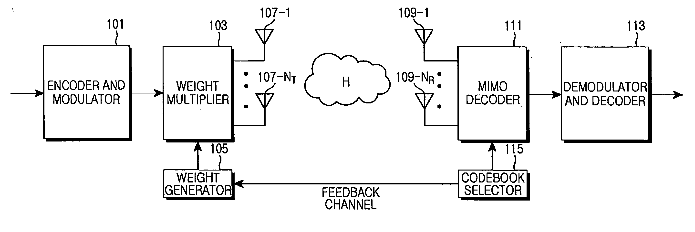
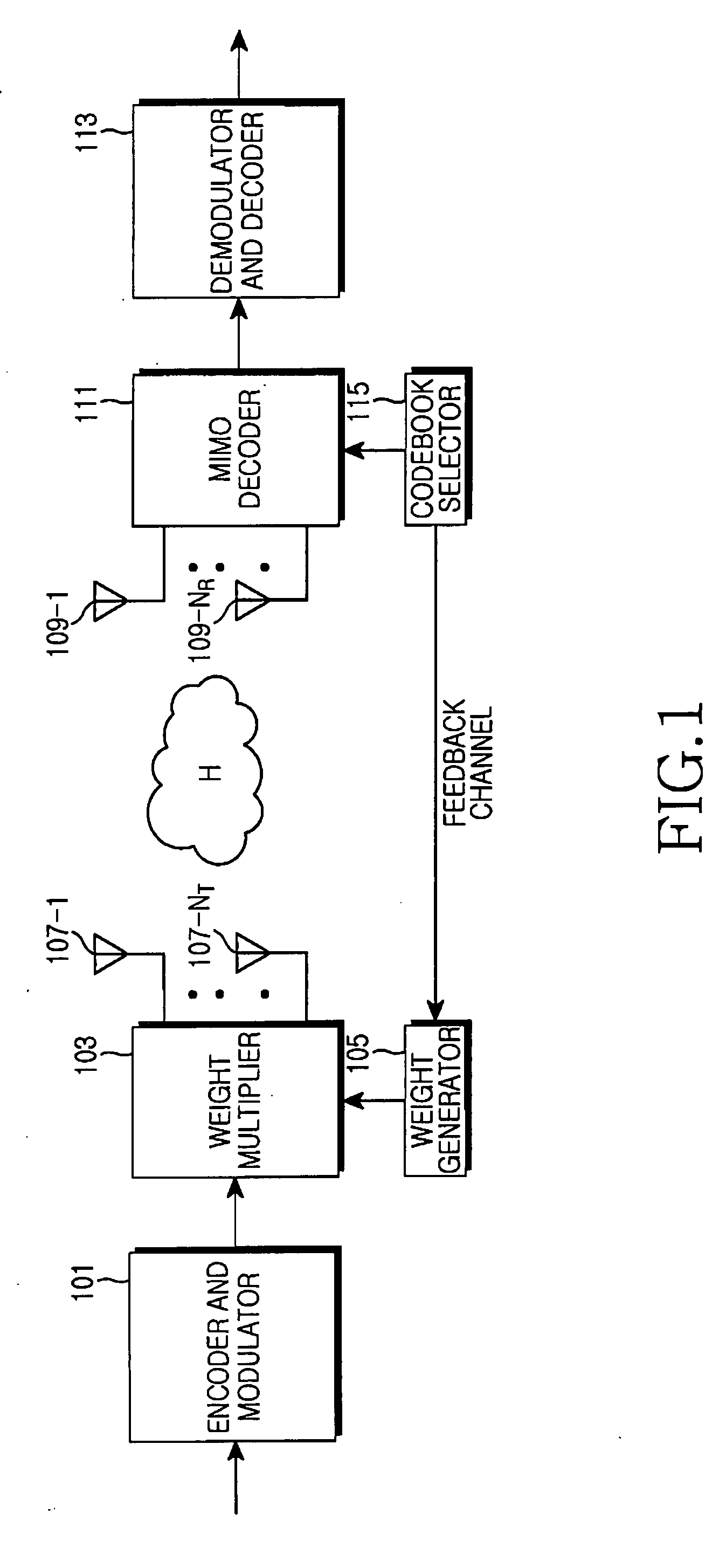
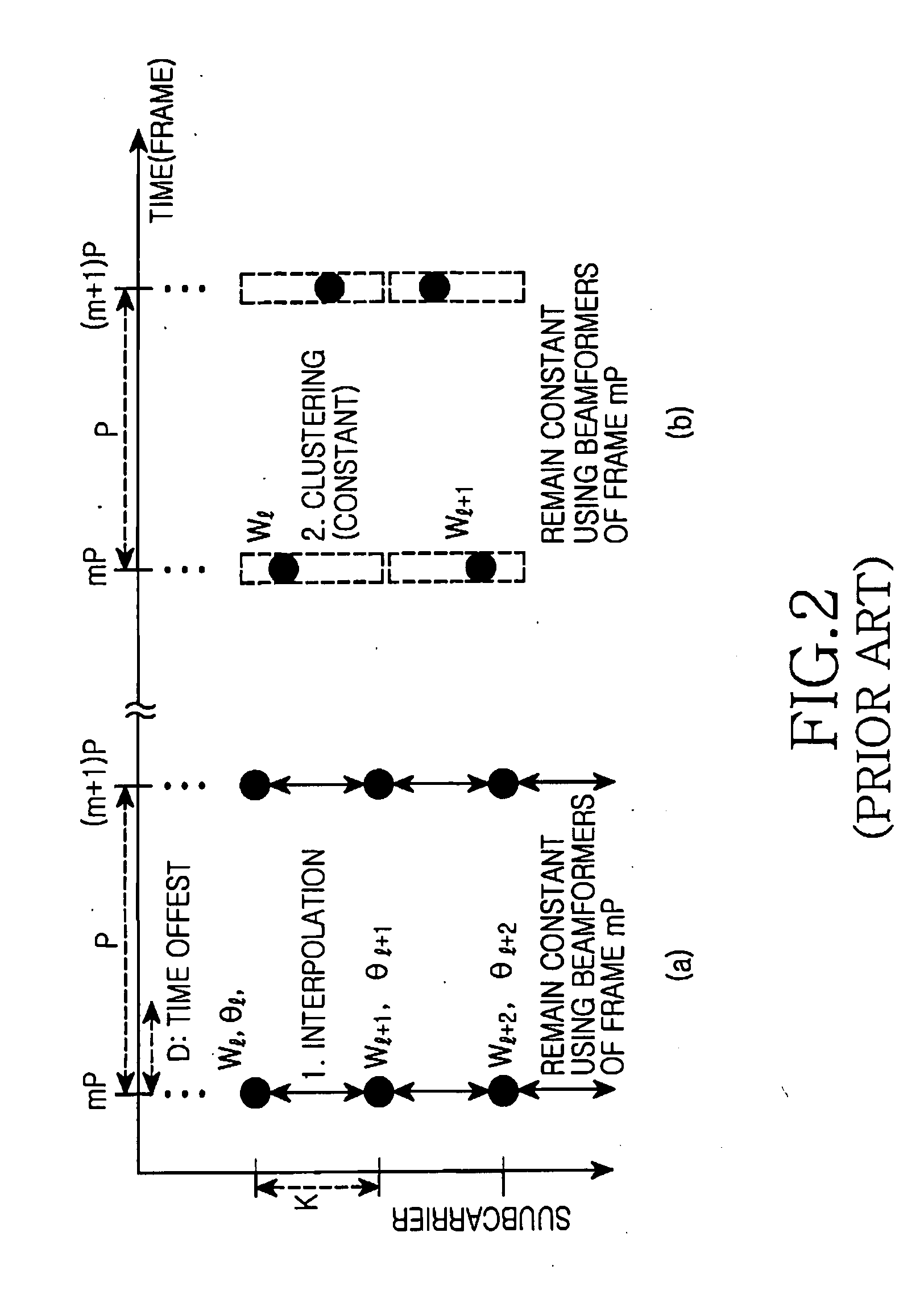
[0041] The present invention provides a method of performing beamforming, taking a time-variant channel into account in a codebook-based transmission beamforming system. The present invention provides a two-dimensional interpolation technique based on the idea that the beamforming vector of a subcarrier is correlated with those of adjacent subcarriers and correlated with its past and future beamforming vectors, as well. In the present invention, a receiver forms feedback information based on the channel prediction of a forthcoming channel and sends it to a transmitter, expecting that feedback transmission beamforming information will be applied to the forthcoming channel. The feedback information is ...


PUM


Abstract

An apparatus and method for determining a beamforming vector in a codebook-based transmission beamforming system are provided. In a feedback method for a receiver in a codebook-based transmission beamforming system, forthcoming channel values for a forthcoming period are generated using M present and previous channel estimates. Effective channel gains for all transmission beamforming vectors included in a codebook are calculated using the forthcoming channel values. A codebook index corresponding to the maximum effective channel gains is fed back to a transmitter.

Description

PRIORITY [0001] This application claims priority under 35 U.S.C. § 119 to an application filed in the Korean Intellectual Property Office on Feb. 3, 2006 and assigned Serial No. 2006-10749, the contents of which are incorporated herein by reference. BACKGROUND OF THE INVENTION [0002] 1. Field of the Invention [0003] The present invention relates generally to a codebook-based beamforming system, and, in particular, to an apparatus and method for determining a transmission beamforming vector, taking a time-variant channel into account in a codebook-based Multiple Input Multiple Output (MIMO)-Orthogonal Frequency Division Multiplexing (OFDM) communication system. [0004] 2. Description of the Related Art [0005] A MIMO system with a plurality of transmit antennas and a plurality of receive antennas provides spatial diversity that mitigates the signal level variation of a fading channel. A narrow-band MIMO system can acquire a diversity gain as high as the product of the numbers of transm...

Claims


Application Information

Patent Timeline
IPC IPC(8): H04J3/16
CPCH04B7/0417H04B7/0626H04B7/0639H04L27/2601H04L25/0204H04L25/022H04B7/066
Inventor LEE, JONG-HYEUKCHO, MYEON-KYUNNAM, SEUNG-HOONYUN, JAE-YEUNLEE, YONG-HOONCHUNG, SAE-YOUNGCHOI, JIHOON
Owner KOREA ADVANCED INST OF SCI & TECH
Learn More