Electro-optic display with edge seal

a technology of optical display and edge seal, applied in optics, instruments, static indicating devices, etc., can solve the problems of inadequate service life of these displays, preventing their widespread use, and gas-based electrophoretic media appearing to be susceptible to the same types of problems

Active Publication Date: 2007-09-13
E INK CORPORATION +1
View PDF17 Cites 112 Cited by
  • Summary
  • Abstract
  • Description
  • Claims
  • Application Information

AI Technical Summary

Benefits of technology

[0053] adhesively securing the peripheral portion of the protective la...

Problems solved by technology

Nevertheless, problems with the long-term image quality of these displays have prevented their widespread usage.
For example, particles that make up electrophoretic displays tend to settle, resulting in inadequate service-life for these displays.
Such gas-based electrophoretic media appear to be susceptible to the same types of problems due to particle settling as liquid-based electrophoretic media, when the media are used in an orientation which permits such settling, for example in a sign where the medium is disposed in a vertical plane.
Indeed, particle settling appears to be ...

Method used


Image

  • Electro-optic display with edge seal
  • Electro-optic display with edge seal

Examples


Embodiment Construction

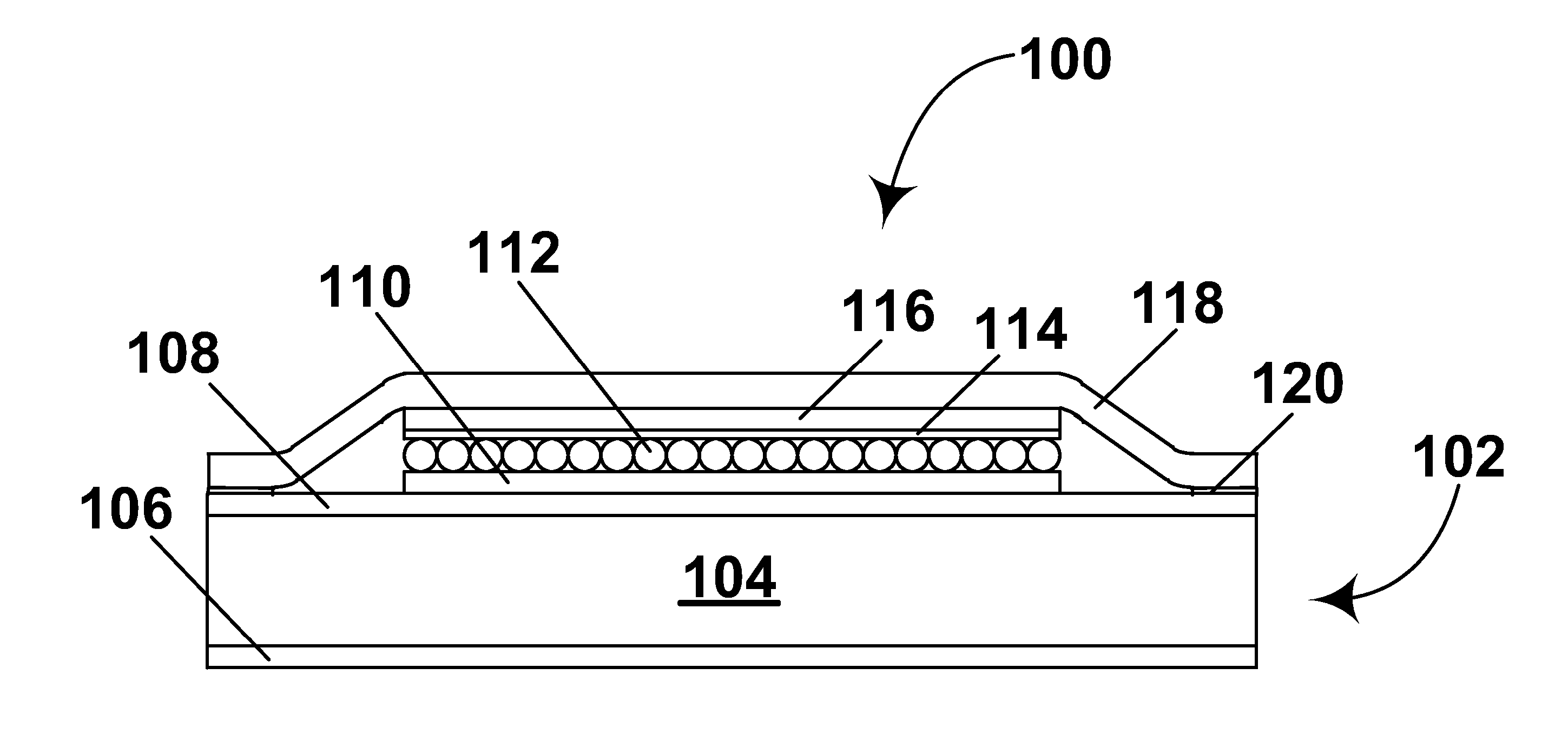
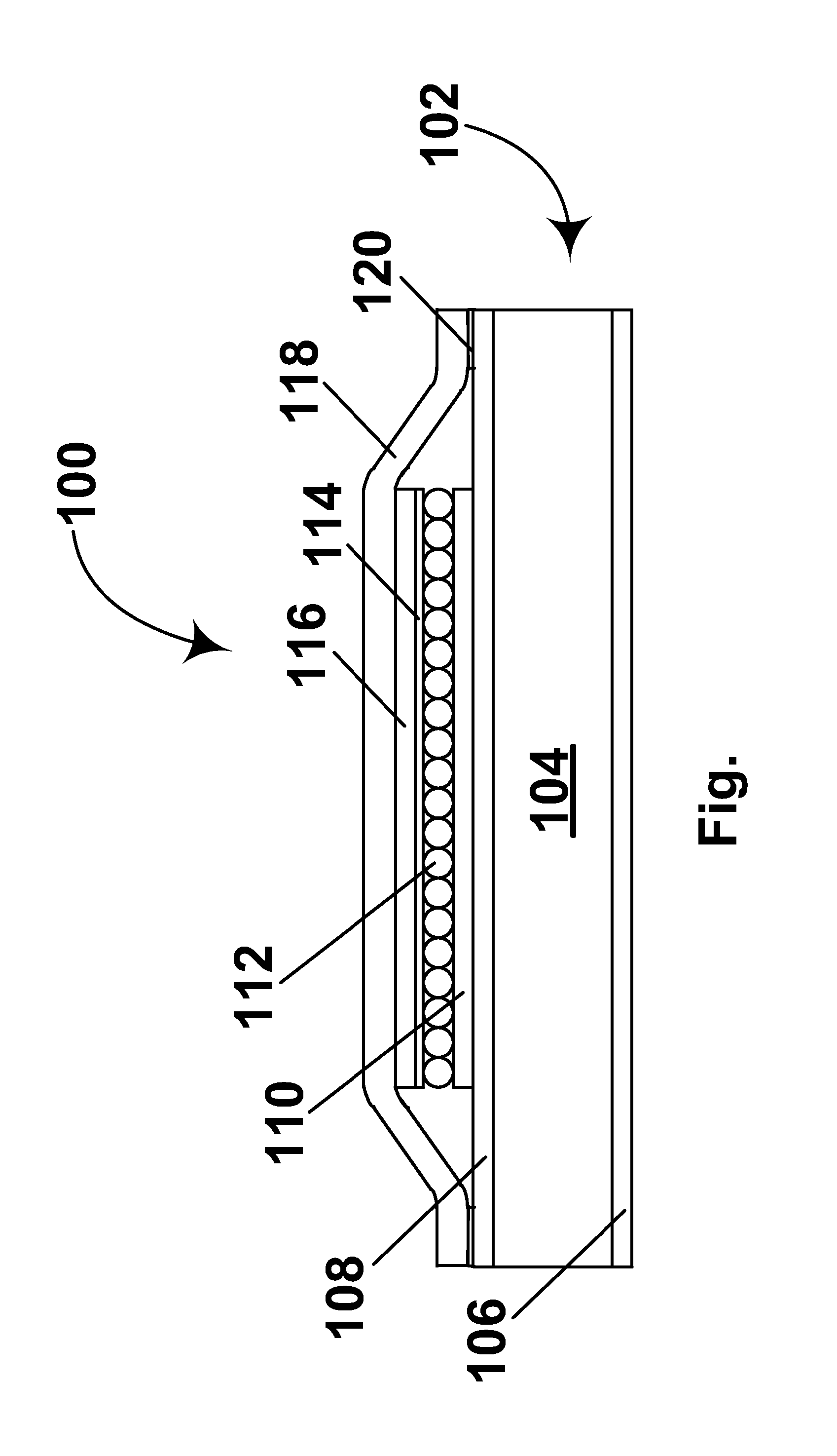
[0055] As already mentioned, the present invention provides a sealed electro-optic display. The display comprises a layer of electro-optic material sandwiched between a backplane and a protective layer. Both the backplane and the protective layer are made larger than the layer of electro-optic material, so that both the backplane and the protective layer have peripheral portions extending beyond the edges (periphery) of the electro-optic material. The peripheral portions of the backplane and protective layer are adhesively secured to each other, thus sealing the layer of electro-optic material from the outside environment.

[0056] It is of course necessary to choose the adhesive material used to secure the backplane to the protective layer to ensure that it does not allow unwanted contaminants to diffuse into the electro-optic material. In particular, since several types of electro-optic material are sensitive to the presence of water, the adhesive material used (as well as the mater...


PUM

PropertyMeasurementUnit
Widthaaaaaaaaaa
Widthaaaaaaaaaa
Acoustic impedanceaaaaaaaaaa

Abstract

An electro-optic display (100) comprises a backplane (102); an electro-optic layer (112) adjacent the backplane (102), the electro-optic layer (112) being smaller than the backplane (102) so as to leave a peripheral portion of the backplane extending beyond the edges of the electro-optic layer (112); and a protective layer (118) disposed on the opposed side of the electro-optic layer (112) from the backplane (102), a peripheral portion of the protective layer (118) extending beyond the edges of the electro-optic layer and being adhered (at 120) to the backplane (102).

Description

REFERENCE TO RELATED APPLICATIONS [0001] This application claims benefit of U.S. Application Ser. No. 60 / 767,186, filed Mar. 9, 2006. [0002] This application is also related to: [0003] (a) U.S. Pat. No. 6,982,178, issued Jan. 3, 2006, on application Ser. No. 10 / 249,957, filed May 22, 2003, and claiming benefit of Application Ser. No. 60 / 319,300, filed Jun. 18, 2002, and Application Ser. No. 60 / 320,186, filed May 12, 2003; [0004] (b) copending application Ser. No. 10 / 605,024, filed Sep. 2, 2003 (Publication No. 2004 / 0155857), and claiming benefit of Application Ser. No. 60 / 319,516, filed Sep. 3, 2002; [0005] (c) U.S. Pat. No. 7,110,164, issued Sep. 19, 2006 on application Ser. No. 10 / 904,063, filed Oct. 21, 2004, which is a continuation-in-part of the aforementioned application Ser. Nos. 10 / 249,957 and 10 / 605,024, and which claims benefit of Application Ser. Nos. 60 / 481,553, 60 / 481,554 and 60 / 481,557, all filed Oct. 24, 2003, Application Ser. No. 60 / 481,564, filed Oct. 27, 2003, and ...

Claims


Application Information

Patent Timeline
IPC IPC(8): G09G3/34G02F1/167G02F1/16755G02F1/1679
CPCG02F1/1334G02F1/1339G02F1/167G02F1/1391G02F1/141G02F1/1341G02F1/1679G02F1/16755
Inventor ZEHNER, ROBERT W.BURNS, SEAMUS EWAN
Owner E INK CORPORATION
Why Eureka
Try Eureka