
Multi-screen synthesizing display apparatus and method
a display apparatus and multi-screen technology, applied in the field of multi-screen display apparatus and a multi-screen display data synthesizer, can solve the problems of low efficiency of display windows, unnecessary write-in operations into video memory, and consumption of extra processing resources and memory bandwidth, so as to achieve the effect of increasing the performance of various kinds of electronic devices with display ability, reducing the overhead of processing and memory bandwidth, and relatively low consumption of processing resources
- Summary
- Abstract
- Description
- Claims
- Application Information
AI Technical Summary
Benefits of technology
Problems solved by technology
Method used
Image

Examples
Embodiment Construction
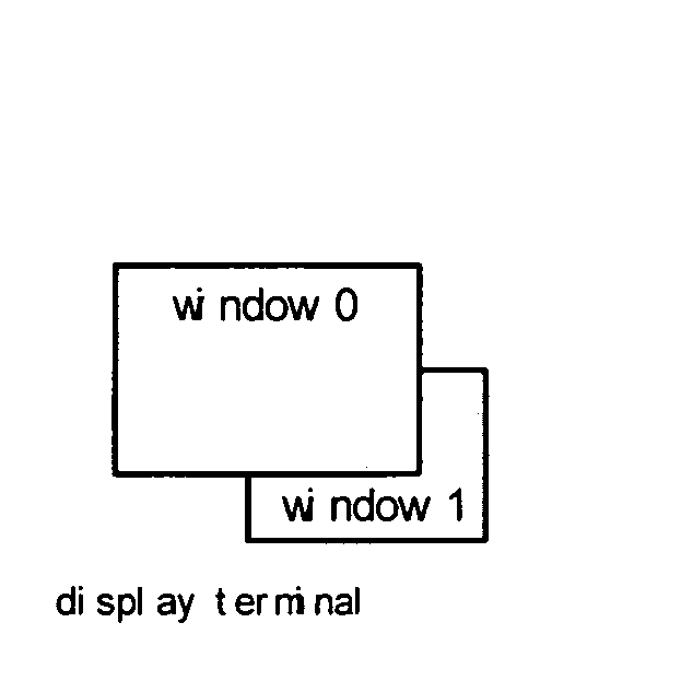
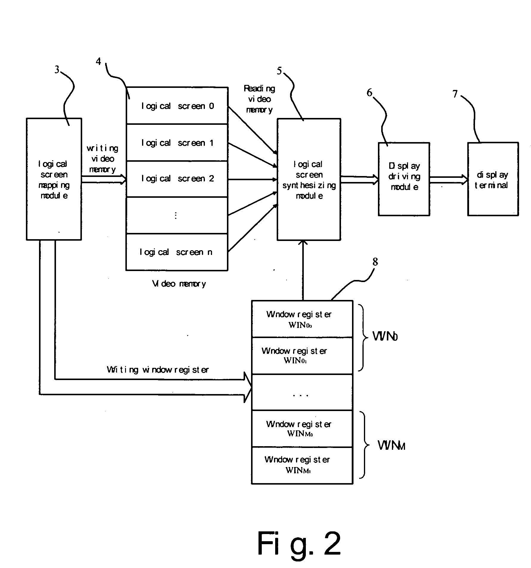
[0012]FIG. 2 is a block diagram showing the multi-screen synthesizing display system according to the present invention. The system comprises a logical screen mapping module 3, a video memory 4, a logical screen synthesizing module 5, a display driving module 6, a display terminal 7 and a window register stack 8. The video memory 4 is divided into a plurality of logically separate blocks 0-N. The logical screen mapping module 3 may be a CPU which performs a program embedded therein, or may be other hardware circuits. A plurality of windows may be displayed on the display terminal 7. All the windows needed to be displayed on the display terminal are mapped onto one or more said logical blocks in the video memory 4 by the logical careen mapping module 3, thus, these mapped logical blocks are revered to as logical screens 0-N. For example, if the display terminal has a resolution 1280×1024, and the word length of display data is 16 bits, then the logical screens 0-n correspond to (N+1)...
PUM
 Abstract
Description
Claims
Application Information