
Hose Clamp Tool

a hose clamp and tool technology, applied in the direction of wire tools, screwdrivers, manufacturing tools, etc., can solve the problems of difficult, if not virtually impossible, use of the second hand to hold the hose clamp

Inactive Publication Date: 2007-10-04
TEETERS DAVID
View PDF39 Cites 13 Cited by
  • Summary
  • Abstract
  • Description
  • Claims
  • Application Information

AI Technical Summary

Problems solved by technology

In those instances where the hose clamp is located in a hard-to-reach position, using one's second hand to hold the hose clamp may be difficult if not virtually impossible.

Method used


Image

  • Hose Clamp Tool
  • Hose Clamp Tool
  • Hose Clamp Tool

Examples


Embodiment Construction

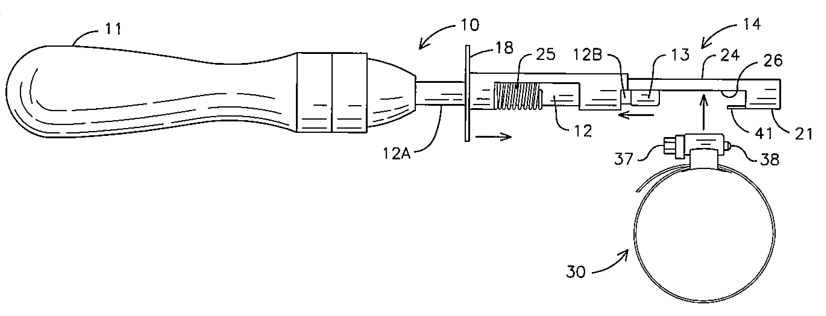
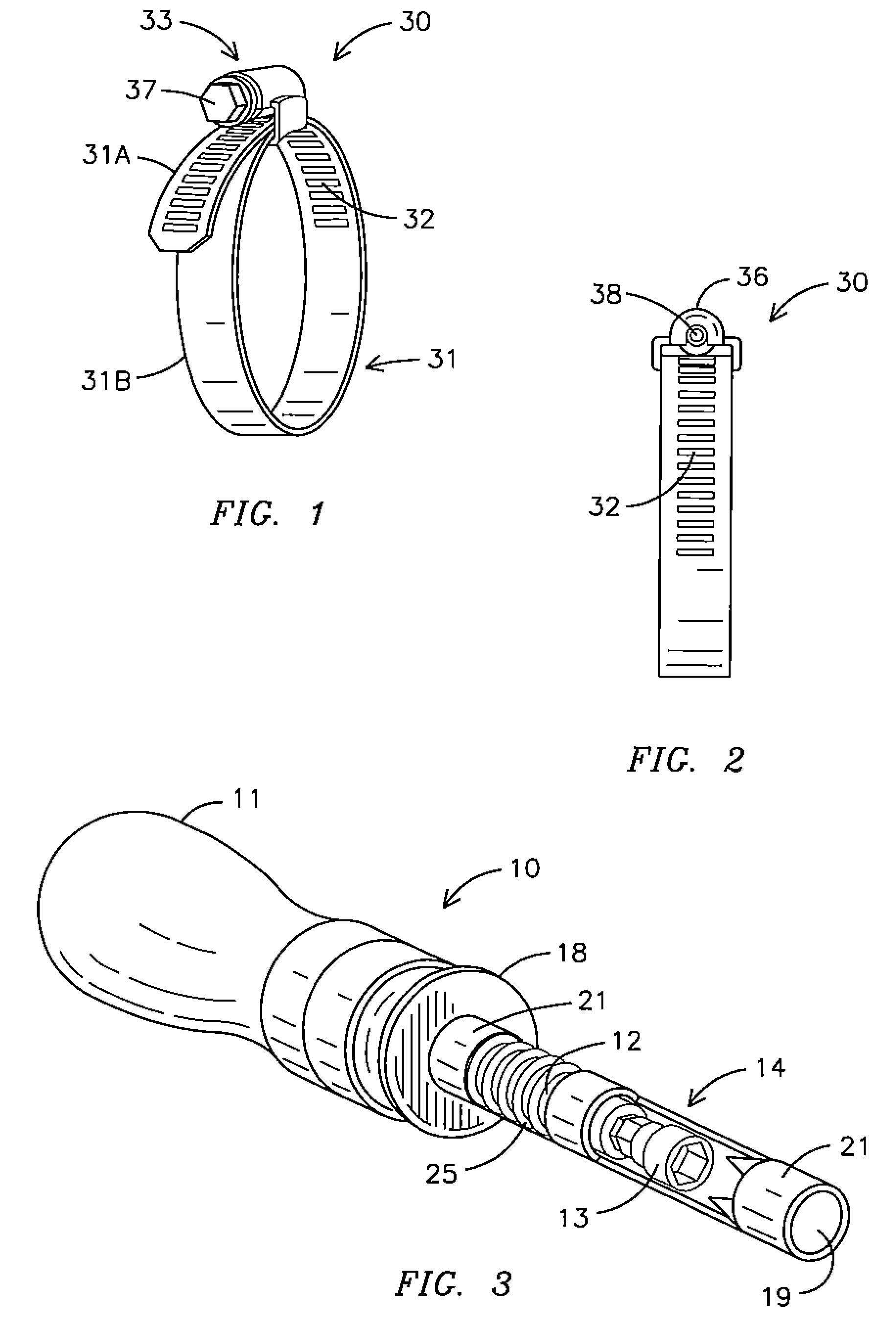
[0021]A hose clamp 30 is illustrated in FIGS. 1 and 2, and includes a metal strip 31 having a first portion 31A rolled over the top of a second portion 31A in a generally circular configuration for receiving a hose (not shown). The first portion 31A and second portion 31B are secured together, in sliding relationship to one another, by an anchor 36, which also secures a bolt 33 to the first portion 31A of the metal strip 31. The bolt 33 has threads (not shown) that are positioned in mating relationship with slots 32 on the first portion 31A of the metal strip 31. The bolt 33 has a head 37 for receiving a tool such as a screwdriver, ratchet, wrench or any other tool used to rotate the bolt 33. When one rotates the bolt 33, the threads engage metal strip 31 at the slots 32 causing the clamp 30 to tighten or loosen depending on which direction the bolt 33 is rotated.

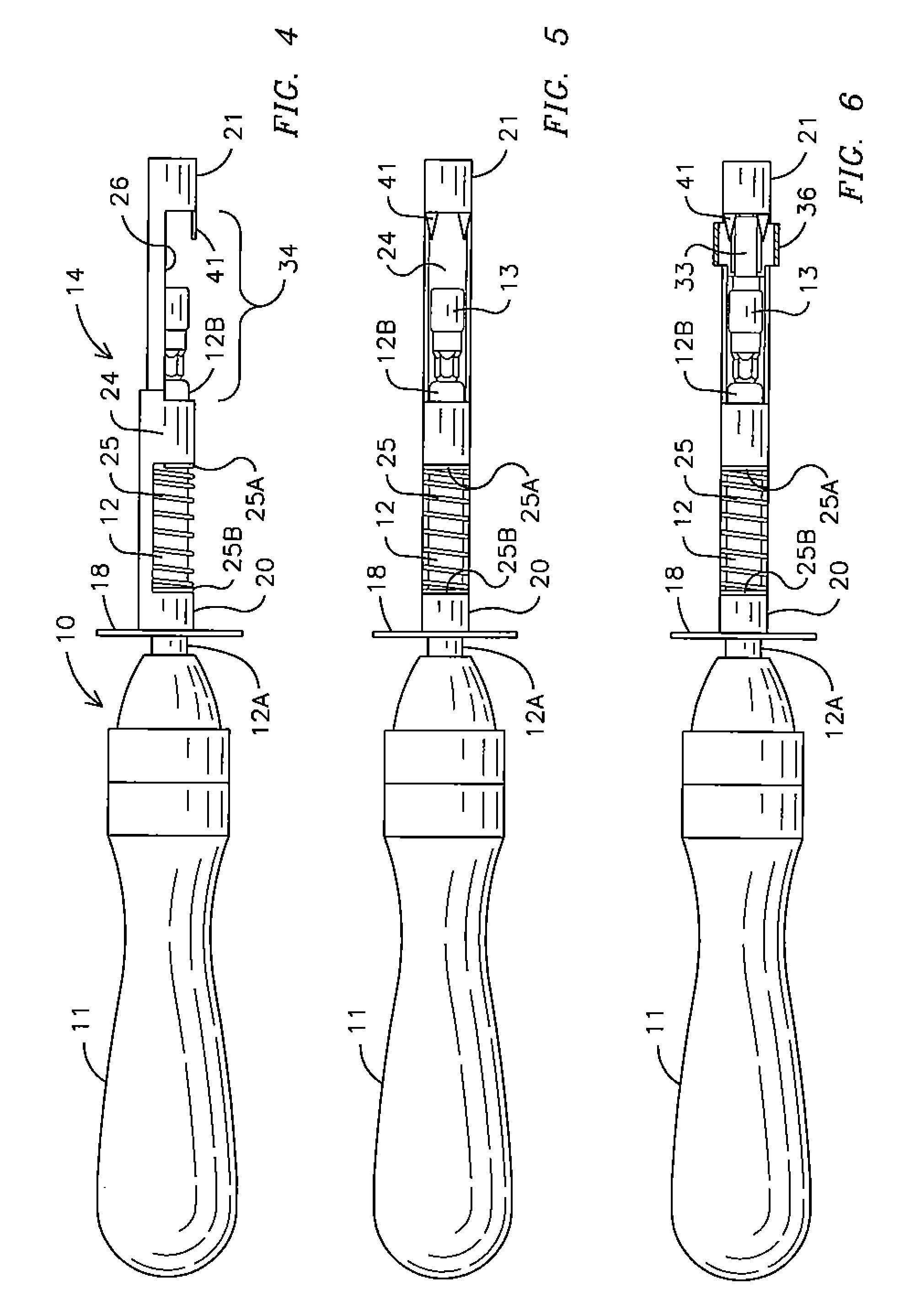
[0022]The invention for a hose clamp tool 10 is depicted in FIGS. 3 through 5, and includes a shaft 12 mounted to a handl...


PUM


Abstract

A hose clamp tool for engaging and supporting a hose clamp has a handle a shaft operable connected to the handle. A support member is positioned in spaced relation to the shaft and supported there on by a biasing member that biases the support member toward the tool handle. The support member includes a first shoulder disposed toward the handle and a second shoulder spaced from the first shoulder toward a second end of the shaft. When support member is biased away from the handle, a gap is formed between the second end of the shaft and the second should of the support for receiving a bolt on the hose clamp. The second end of the shaft engages the bolt and the support member is released and biased toward the handle so the second shoulder engages the hose clamp at an end of the bolt opposite the bolt head.

Description

CROSS-REFERENCE TO RELATED APPLICATIONS[0001]This application claims priority to U.S. Provisional Application No. 60 / 787,574 filed Mar. 30, 2006.BACKGROUND OF THE INVENTION[0002]This invention pertains to tools used to install, tighten, loosen or remove hose clamps. More specifically, the invention relates to tools that enable one to access a hose clamp in hard to reach positions and / or tools that enable one to install or remove a hose clamp using only one hand.[0003]A hose clamp typically includes a pliable metal strip that has two ends overlapping one another forming a circle. An anchor secures the overlapping sections of the metal strip together. In addition, a bolt is secured to the metal strip at the anchor. Threads on the bolt are positioned in mating relationship with slots formed in the metal strip. Accordingly, when a drive tool as a screw driver or wrench engages a head on the bolt and rotates the bolt, the ends of the strip move relative to one another tightening or loose...

Claims


Application Information

Patent Timeline
Patent Type & Authority Applications(United States)
IPC IPC(8): B25B27/10
CPCB25B25/005B25B15/02
Inventor TEETERS, DAVID
Owner TEETERS DAVID
Learn More