Sheet feeding apparatus and image forming apparatus

a technology of feeding apparatus and forming apparatus, which is applied in the direction of transportation and packaging, thin material processing, and article separation, etc., can solve the problems of skew feeding, affecting the forming effect, and unable to determine whether or not the sheet is positioned within the predetermined range,

Active Publication Date: 2007-10-04
CANON KK
View PDF9 Cites 70 Cited by
  • Summary
  • Abstract
  • Description
  • Claims
  • Application Information

AI Technical Summary

Benefits of technology

[0011]In view of the foregoing, an object of the invention is to provide an image forming apparatus, in which the rotating speed of the fan can be set so as to become the optimum air quantity irrespective of the fluctuation of the fan itself, the aged deterioration of the fan characteristics, and the like and the fan can be stabilized at an optimum rotating speed.

Problems solved by technology

However, it cannot be determined whether or not the sheet positioned within the predetermined range becomes an optimum dealing state.
However, even if the rotating speed of the separating fan is set in each sheet material to obtain the proper air blowing quantity, sometimes the proper rotating speed is not stably obtained due to a fluctuation of the fan itself, aged deterioration of fan characteristics, and voltage drop caused by bundle conductors.
In this case, for example, when the sheet is thin, or when sheet is made of the light material, the rotating speed of the separating fan is faster than the target value, the sheet dealing state is not stabilized, which possibly results in a trouble such as sheet jam, skew feeding, position shift, a flaw, folded sheet, and dirt.
When the sheet is thick, or when sheet is made of the heavy material, the rotating speed of the separating fan is slower than the target value, the proper air does not flow between the sheets, which possibly results in a trouble such as conveyance of overlapped sheets.
In such cases, the rotating speed of the separating fan becomes improper value, which possibly results in the trouble such as the conveyance of overlapped sheets, the skew feeding, the position shift, the flaw, the folded sheet, and the dirt.

Method used


Image

  • Sheet feeding apparatus and image forming apparatus
  • Sheet feeding apparatus and image forming apparatus
  • Sheet feeding apparatus and image forming apparatus

Examples


Embodiment Construction

[0038]Exemplary embodiments of the invention will be described in detail with reference to the drawings. However, in the following embodiments, dimensions, materials, and shapes of components and a relative arrangement of the components should appropriately be changed depending on a configuration of an apparatus to which the invention is applied and various conditions. Accordingly, unless otherwise specifically described, the scope of the invention is not limited to the embodiments.

[0039](Image Forming Apparatus)

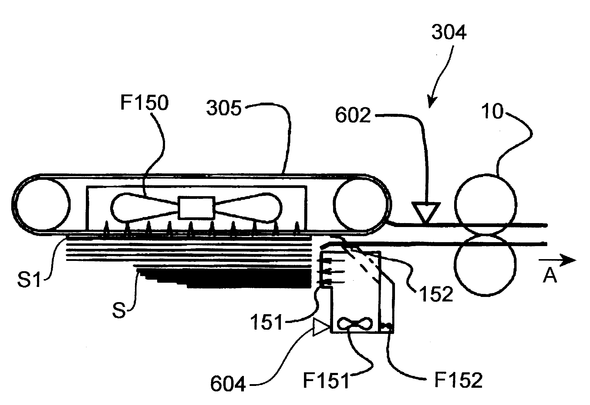
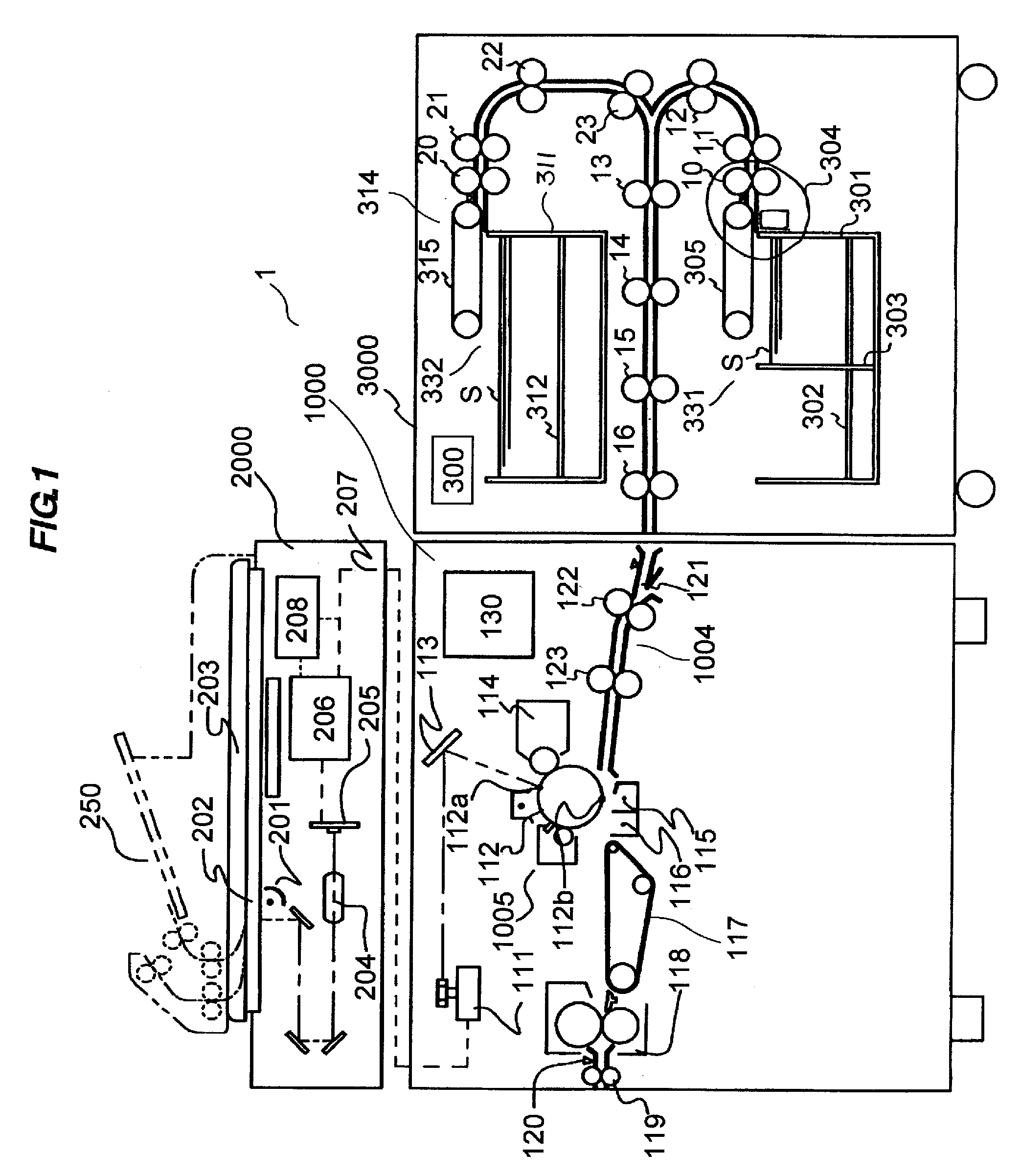
[0040]A schematic configuration of an image forming apparatus shown in FIG. 1 will be described below. FIG. 1 is a sectional view illustrating a schematic configuration of the image forming apparatus having a sheet feeding apparatus;

[0041]Referring to FIG. 1, an image forming apparatus 1 includes a printer body 1000 and a scanner 2000 arrange on an upper surface of the printer body 1000. The image forming apparatus 1 also includes a sheet feeding apparatus 3000 which feeds t...


PUM


Abstract

An image forming apparatus has a sheet feeding apparatus which separates and feed a sheet one by one using a loosening fan which blows air from an air blowing portion for loosening the sheet on a tray. The rotating speed of the sheet loosening fan is adjusted while the sheet supported by the tray is not located in front of a position where the air is blown from the air blowing portion.

Description

BACKGROUND OF THE INVENTION[0001]1. Field of the Invention[0002]The present invention relates to an image forming apparatus equipped with a sheet feeding apparatus that feeds a sheet.[0003]2. Description of the Related Art[0004]Conventionally the image forming apparatus such as a copying machine and a printer is equipped with the sheet feeding apparatus. The sheet feeding apparatus feeds the sheet cut into a predetermined size to a transfer position one by one in order to transfer a toner image, formed on a photosensitive member, onto the sheet at the transfer position.[0005]For example, Japanese Patent Application Laid-Open No. 7-196187 discloses a sheet feeding apparatus having a configuration in which air is blown to the sheet from one end side in a conveyance direction of the sheets loaded in an accommodation box using a separating fan and the floating sheet is adsorbed to and conveyed by a conveyance belt.[0006]However, a floatation amount depends on a material (thickness or we...

Claims


Application Information

Patent Timeline
Patent Type & Authority Applications(United States)
IPC IPC(8): B65H3/14
CPCB65H1/14B65H3/48B65H2511/20B65H2515/212B65H2801/21B65H2220/01B65H2220/04B65H2220/02B65H2515/20
Inventor MATSUMOTO, YUZOFUKUSAKA, TETSUROIKEDA, TARO
Owner CANON KK
Why Eureka
Try Eureka