

Testing an Electronic Device Having a Keypad by Simultaneously Pressing Several Keys
- Summary
- Abstract
- Description
- Claims
- Application Information
AI Technical Summary
Benefits of technology
Problems solved by technology
Method used
Image

Examples
Embodiment Construction
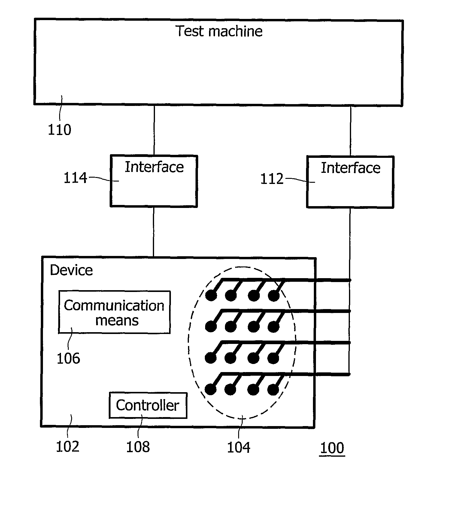
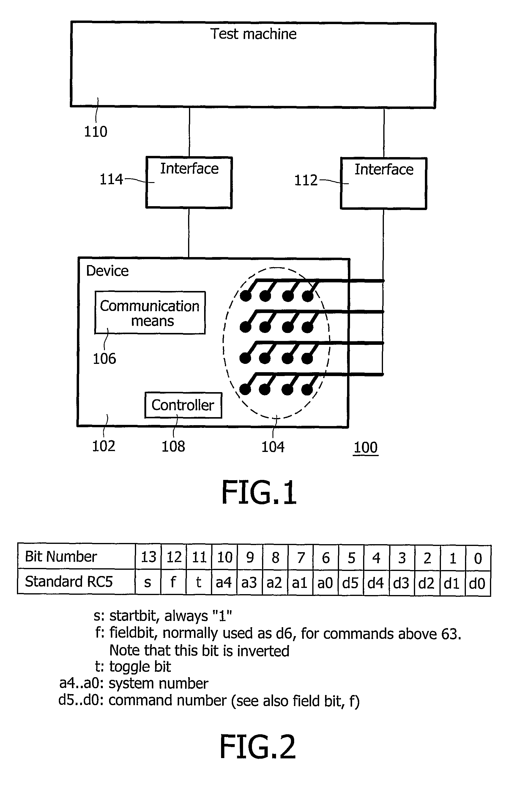
[0022]FIG. 1 is a block diagram of a test system 100 in the invention. System 100 comprises an electronic device 102 with a plurality of keys 104. Device 102 comprises, e.g., a remote control device for control of consumer electronics (CE) equipment. Each one of keys 104 invokes a respective control functionality of device 102 upon being pressed in operational use of device 102. For example, one key may implement the “channel-up” functionality, another the “channel-down” functionality, yet another is the “mute” button. Some of the control functionalities may require a certain combination of keys to be pressed in sequence or together. For remote control of compatible CE equipment (not shown), device 102 has communication means 106, e.g., comprising an infrared (IR) transmitter or a radio-frequency (RF) transmitter. Device 102 further has a controller 108 that converts the key presses into IR or RF commands in operational use of device 102.
[0023] Test system 100 further comprises a t...
PUM
 Abstract
Description
Claims
Application Information