
Electric interference limitation

Active Publication Date: 2015-11-26
VACON OY
View PDF93 Cites 2 Cited by
  • Summary
  • Abstract
  • Description
  • Claims
  • Application Information

AI Technical Summary

Benefits of technology

The patent avoids the resonance frequencies of the installation impedance, which reduces the minimum common mode current, minimizes the warming effect on components, and reduces interference with other devices connected to the power grid.

Problems solved by technology

Most severe current of this kind is the current between an electric power distribution grid and the ground, excited by a power electronic appliance connected to the public network, due to that the high frequency ground current may be a source of interference to other electric devices connected to the same grid.
At these frequencies the common mode current may be very high, causing e.g. overheating in the components at the current path.

Method used


Image

  • Electric interference limitation
  • Electric interference limitation
  • Electric interference limitation

Examples


Embodiment Construction

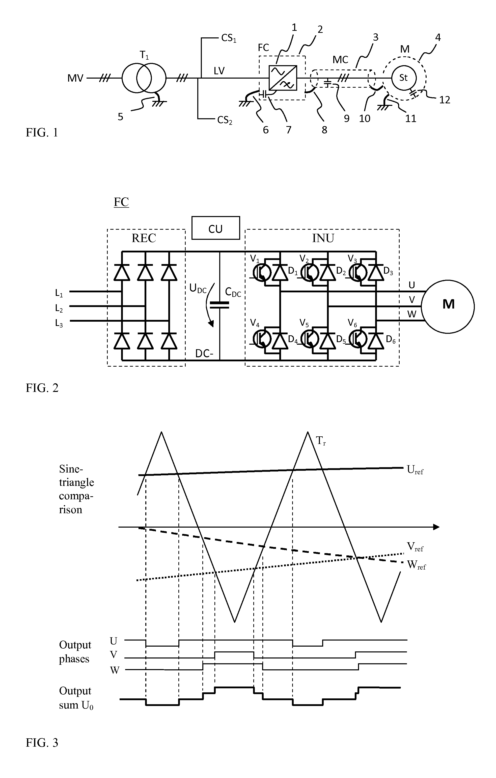
[0019]FIG. 1 presents an electric installation in a simplified one-line diagram form. MV means a medium voltage (e.g. 50 kV) power distribution grid, which is stepped down by a power by a transformer T1 to a low voltage (e.g. 400 V) service voltage LV for a power electronics consumer FC and other end customers CS1, CS2, near the consumer location. The low voltage grid is normally grounded in the transformer (e.g. by connecting the star point of secondary windings to the ground by a wire 5).

[0020]The power electronics consumer in this example is a frequency converter FC, which is connected to a load motor M by a power cable MC. The frequency converter FC consists of a power electronics part 1 and an at least partly metallized housing 2, which is connected to ground by a wire 6. In this kind of installation a screened type power cable MC is normally used, and the screen is connected to the grounded metal housings at both ends by wires 8, 10. The motor metal housing is connected to gro...


PUM


Abstract

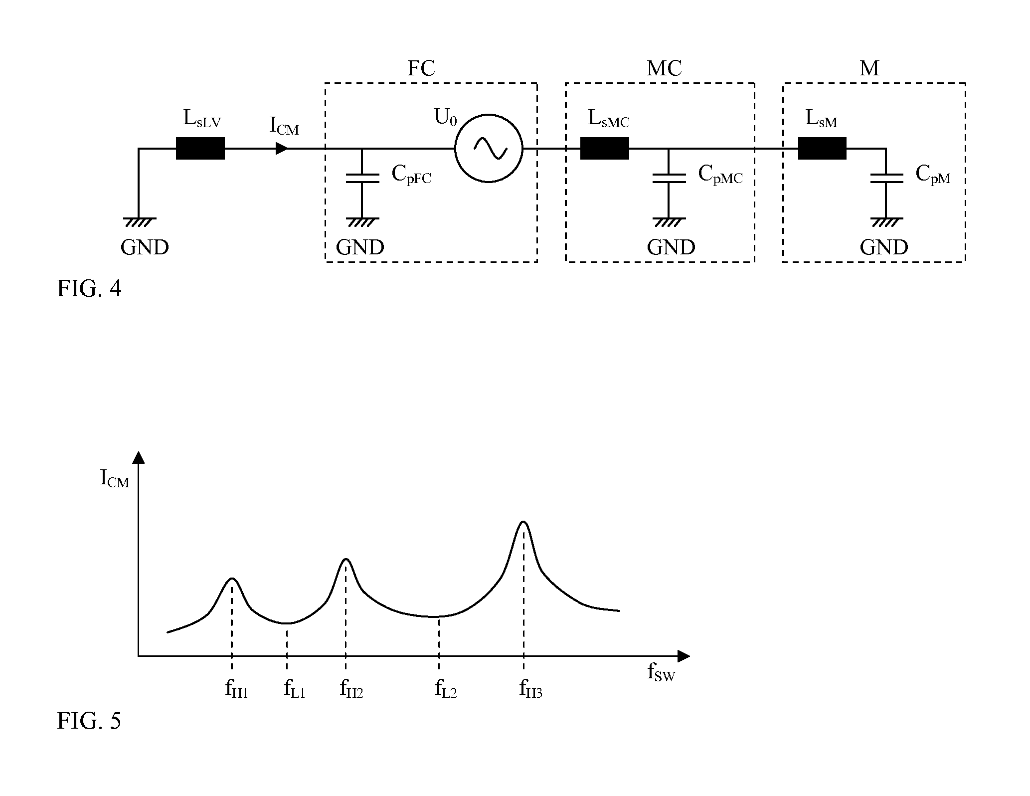
A method and an arrangement for limiting the interference to a common electric power network, generated by a power electronics device, e.g. a frequency converter, which power electronics device comprises of at least one switch type component being able to change the output voltage value at a predefined permissible switching frequency range. The method comprises scanning through the permissible switching frequency range, recording measured common mode current values as a function of the switching frequency, and setting the final switching frequency of the switch type component out of a value where a local maximum value of the common mode current has been recorded.

Description

FIELD OF TECHNOLOGY[0001]This invention relates to a method and arrangement for limiting the interference to a common electric power network, generated by a power electronics device, especially generated by a frequency converter.BACKGROUND AND DESCRIPTION OF THE PRIOR ART[0002]Power electronics is used in wide range of applications for controlling and converting of electric power. E.g. adjustable speed electric motor drives, consisting of a frequency converter controlled AC motor, are used widely in many industrial applications ranging from fractional kW to several MW power levels. Modern power electronic appliances are based on rapid semiconductor devices, e.g. insulated gate bipolar transistors (IGBT), used as switches in various power conversion topologies. It is always beneficial to have as low as possible internal power losses in a device, which is the reason for preferring fast components in power electronics.[0003]The fast switching of a power component means fast voltage slo...

Claims


Application Information

Patent Timeline
IPC IPC(8): H02M1/12H02M1/08H02P23/00H02M5/458
CPCH02M1/12H02M5/458H02M2001/123H02P23/0081H02M1/08H02M5/27H02P23/26H02M1/123
Inventor SODO, NICKLAS
Owner VACON OY
Learn More