Device for laying a flexible material web

Inactive Publication Date: 2006-11-16
SAURER GMBH & CO KG
View PDF7 Cites 5 Cited by
  • Summary
  • Abstract
  • Description
  • Claims
  • Application Information

AI Technical Summary

Benefits of technology

[0020] According to a preferred embodiment of the device according to the invention, the material web could also be transported to the deposit rollers between two transport belts. The advancing speed of the material web during transport on the transport belt or between two transport belts could be equal to the advancing speed of the transport belt or belts. During transport between two transport belts, they could form a pressure zone, whereby a substantially seamless supply of the material web between two transport belts is achieved, where the material web lies on one transport belt and is covered by the other. In this way it is ruled out on the one hand that the material web slips and on the other hand that the material web is contaminated or otherwise exposed to external influences. The equality of the speed of the transport belt to the speed of the material web transported on the transport belt entails the advantage that electrostatic effects are substantially avoided and the material itself is protected. The reduction of friction is above all of significance in regard to depositing the material web onto the pr

Problems solved by technology

Starting from U.S. Pat. No. 6,155,551 it has been recognized that the

Method used


Image

  • Device for laying a flexible material web
  • Device for laying a flexible material web
  • Device for laying a flexible material web

Examples


first embodiment

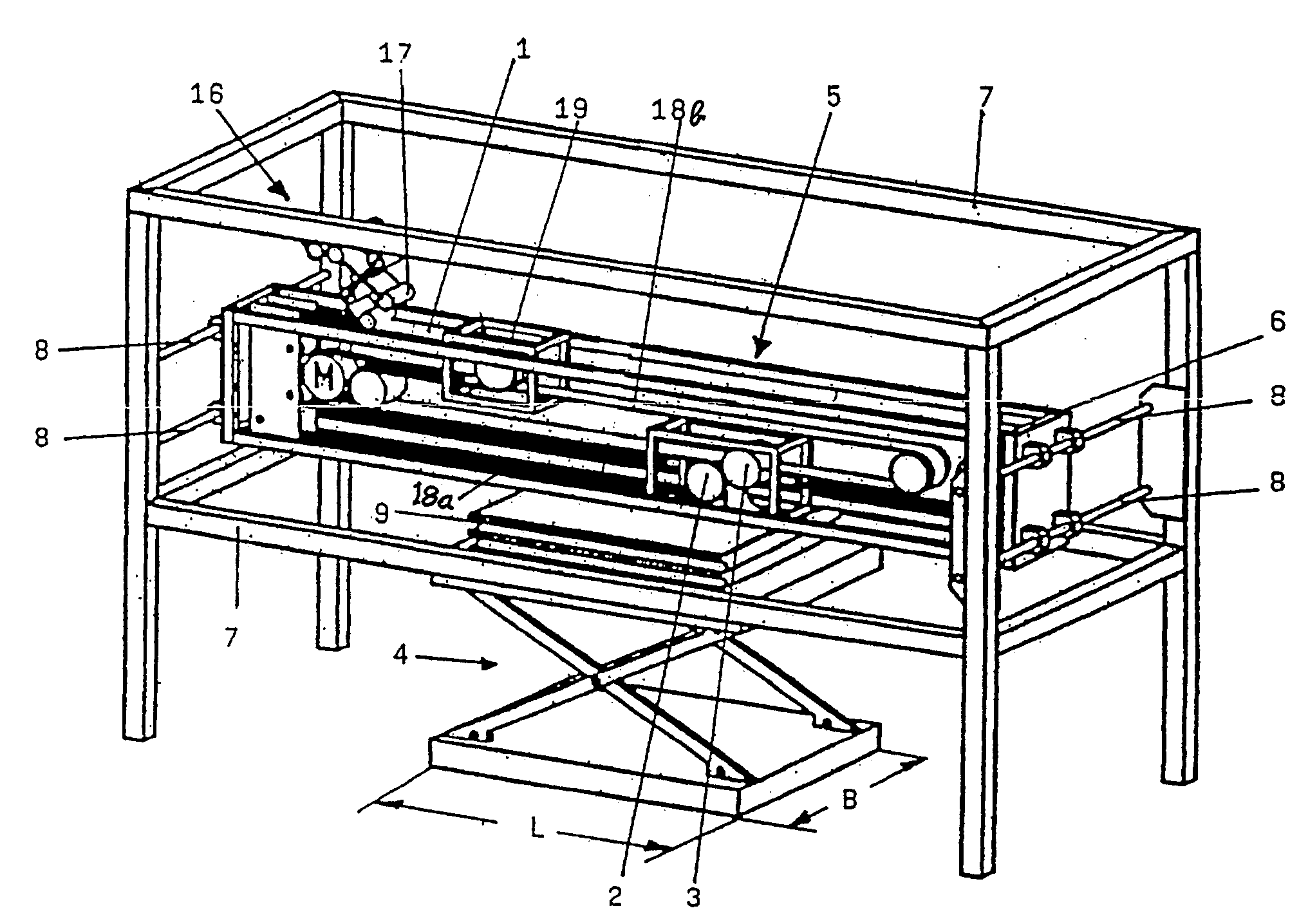
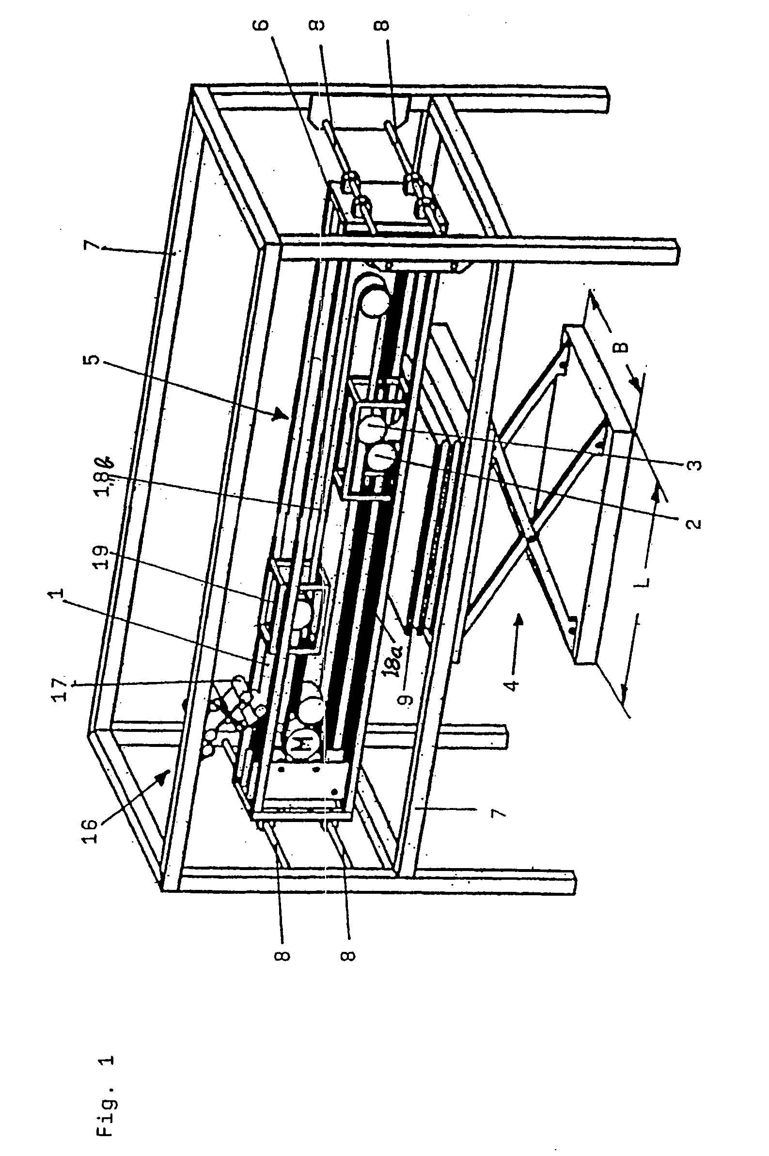
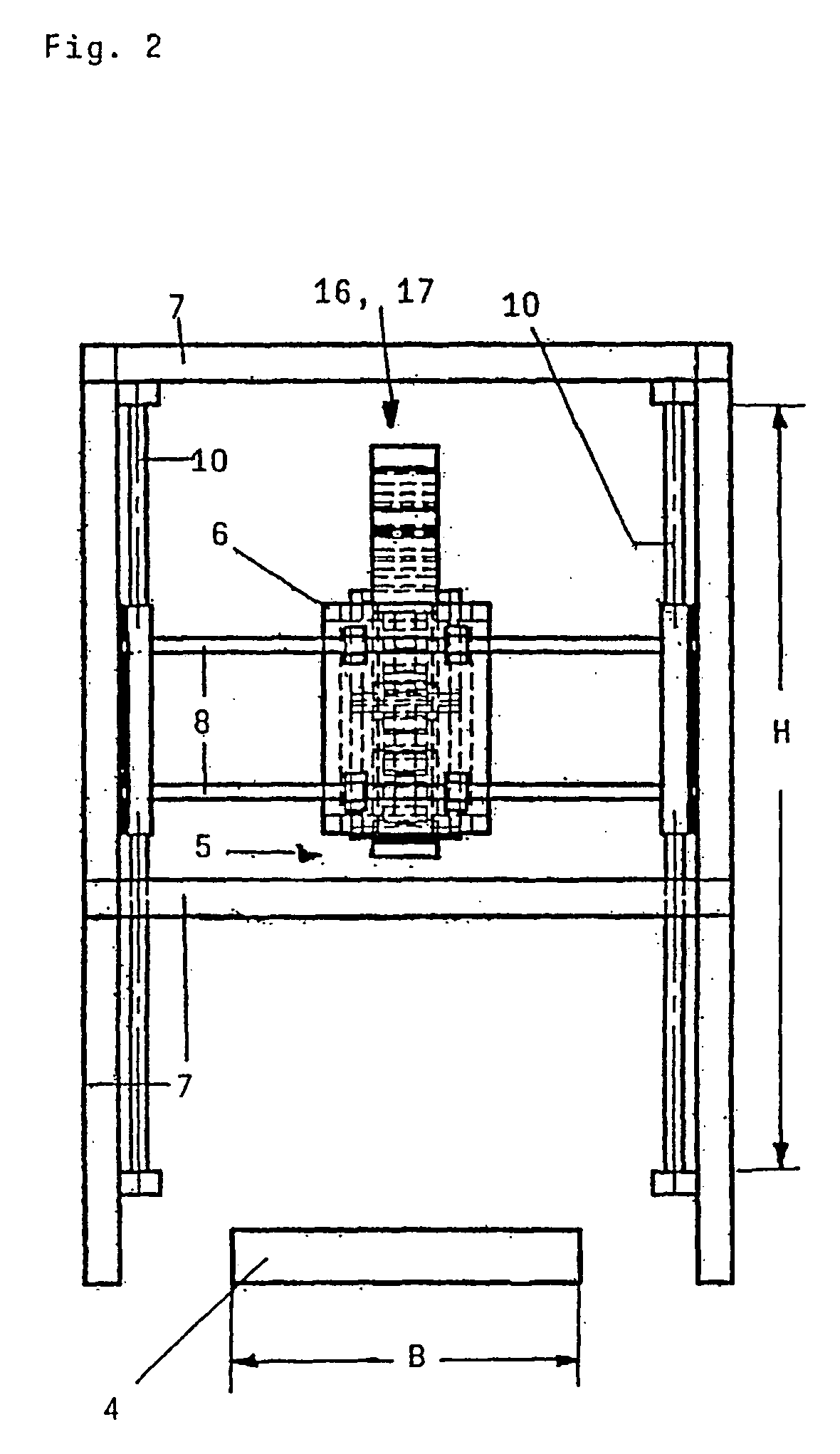
[0033] In FIG. 1, a first embodiment is shown, where the point of deposit 4 is embodied by a lifting table which can be adjusted with regard to its height and is traversed downwards as the stack 9 grows. In FIG. 2, not the point of deposit 4 but rather the deposit carriage 5 can be adjusted with regard to its height H. Disposed on the rack 7 for the height adjustment are vertical guide bars 10 for the frame 6, with which the deposit carriage 5 can be traversed into the suitable position relative to the fixed point of deposit 4.

[0034] From FIG. 3 a third embodiment of the device according to the invention is shown, where two points of deposit 4 are assigned to the deposit carriage 5. In this third embodiment the deposit carriage 5 can be traversed over both deposit lengths L and supplies in succession one point of deposit 4 after another with the material web 1 without protracted interruption.

fifth embodiment

[0035] FIGS. 4 to 7 represent the situation in which, according to a fourth and fifth embodiment, two types of means for holding down the uppermost deposited material web 1 are provided.

[0036] According to FIGS. 4 and 5 the hold-down means comprise a pair of hold-down rollers 11, 12. The hold-down rollers 11, 12 extend approximately from one end face of the rack 7 to the other and can be traversed in the transverse direction together with the deposit carriage 5, where each of the hold-down rollers 11, 12 here clearly projects beyond the deposit width B at the reversing point of the deposit carriage 5.

[0037] A hold-down belt 13 is represented in FIGS. 6 and 7 which in the transverse direction runs around reversing rollers 14, 15 over the entire area of the rack 7. The hold-down belt 13 extends over the deposit length L and the deposit width B of the point of deposit 4 and, in each case at the current height of the uppermost layer of the deposited material web 1 or the stack 9, exten...


PUM

PropertyMeasurementUnit
Lengthaaaaaaaaaa
Pressureaaaaaaaaaa
Flexibilityaaaaaaaaaa

Abstract

A device for laying a flexible material web 1 on a point of deposit 4 and which has at least one pair of deposit rollers 2, 3 that rotate in opposite directions. The deposit rollers 2, 3 form part of a deposit carriage 5 which is reciprocated in a reversible direction over at least the deposit length L of the material web 1. The device is more cost-effective in that the deposit carriage 5 has a smaller width than the point of deposit 4 and is reciprocated in a reversible direction over at least the deposit width B of the point of deposit 4.

Description

CROSS REFERENCE TO RELATED APPLICATION [0001] The present application is a continuation of international application PCT / IB2004 / 003827, filed 7 Sep., 2004, and which designates the U.S. The disclosure of the referenced application is incorporated herein by reference.BACKGROUND OF THE INVENTION [0002] The present invention relates to a device for laying a flexible material web and having at least one pair of deposit rollers rotating in opposite directions, where the material web can be supplied to at least one point of deposit by means of the deposit rollers, where the deposit rollers are a part of the deposit carriage which can be traversed over the deposit length of the material web and with a reversible direction, where the deposit carriage has a smaller width than the point of deposit and can be traversed over the deposit width of the point of deposit and with a reversible direction. [0003] A device of the type under discussion follows from U.S. Pat. No. 6,155,551. There a device...

Claims


Application Information

Patent Timeline
IPC IPC(8): B65H45/103B65H45/105
CPCB65H45/105
Inventor STEYER, PETER
Owner SAURER GMBH & CO KG
Why Eureka
Try Eureka