
Apparatus for electrical signal generation based upon movement and associated methods

a technology of electrical signal and apparatus, applied in the direction of sea energy generation, motors, engine working fluid, etc., can solve the problem that the above-mentioned conventional systems may be inefficient at generating electrical power

Inactive Publication Date: 2007-11-01
HARRIS CORP
View PDF25 Cites 31 Cited by
  • Summary
  • Abstract
  • Description
  • Claims
  • Application Information

AI Technical Summary

Problems solved by technology

Unfortunately, the above described conventional systems may be inefficient at generating electrical power for self-powering applications for movements along multiple degrees of freedom, or for movement sensing systems.

Method used


Image

  • Apparatus for electrical signal generation based upon movement and associated methods
  • Apparatus for electrical signal generation based upon movement and associated methods
  • Apparatus for electrical signal generation based upon movement and associated methods

Examples


Embodiment Construction

[0026] The invention will now be described more fully hereinafter with reference to the accompanying drawings, in which preferred embodiments of the invention are shown. This invention may, however, be embodied in many different forms and should not be construed as limited to the embodiments set forth herein. Rather, these embodiments are provided so that this disclosure will be thorough and complete, and will fully convey the scope of the invention to those skilled in the art. Like numbers refer to like elements throughout, and prime notation is used to indicate similar elements in alternative embodiments.

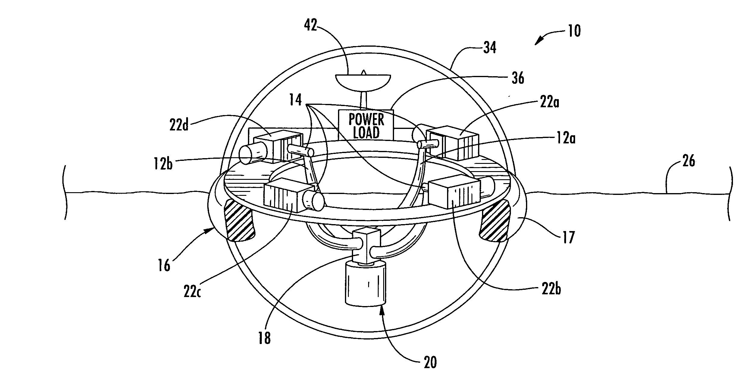
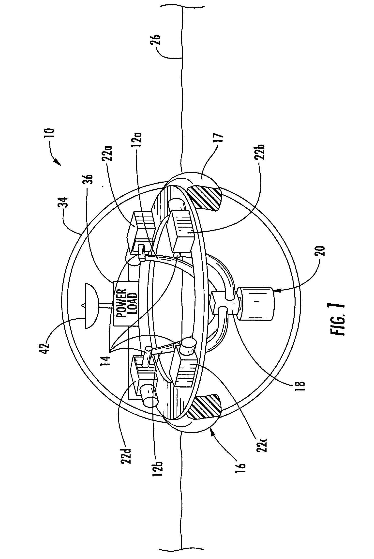
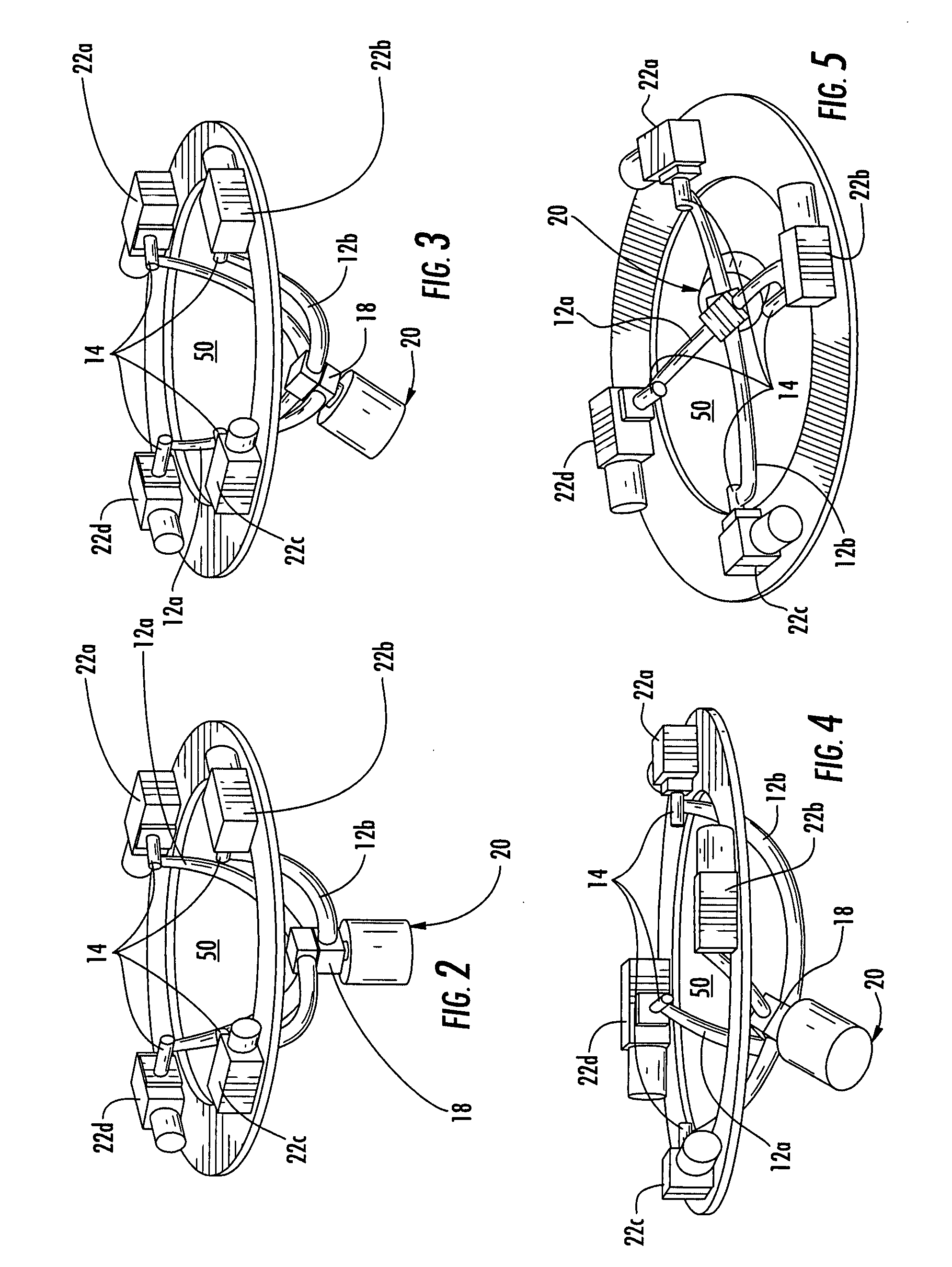
[0027] Referring initially to FIGS. 1-5, an apparatus in the form of a water buoy 10 for generating electrical power in accordance with the invention is now described. The buoy 10 comprises a pair of arcuate swing arms 12a, 12b having respective opposing ends 14 pivotally carried by a base 16 so that the arcuate swing arms are transverse to one another and define a movable crossi...


PUM


Abstract

A generator / sensor may include a pair of arcuate swing arms having respective opposing ends pivotally carried by a base so that the arcuate swing arms are transverse to one another and define a movable crossing point therebetween. A body may be carried by the arcuate swing arms at the crossing point therebetween. At least one electrical generator may be driven by relative movement between the body and the base, such as to generate electrical power or to sense movement, for example. The body may be a pendulum mass or sail responsive to fluid flow.

Description

FIELD OF THE INVENTION [0001] The invention relates to the field of generators and sensors, and, more particularly, to a generator / sensor operated by movement and related methods. BACKGROUND OF THE INVENTION [0002] The relative motion between two bodies may be used to generate electrical power and this technique has been used to power remote sensors such as waterway buoys. Waterway buoys range from simple channel marking devices to complex data gathering sensors that collect information such as wind speed, air temperature, water temperature, wave heights, and the like. For example, a simple channel marking device is illustrated in U.S. Pat. No. 4,423,334 to Jacobi et al. The Jacobi et al. patent discloses a spherical buoy carrying a battery and an arcuate member having two ends surrounded by magnetic loops. A body having two windings at its ends travels along the arcuate member in response to the buoy being moved by wave action. The movement of the body winding through a respective ...

Claims


Application Information

Patent Timeline
Patent Type & Authority Applications(United States)
IPC IPC(8): F03B13/14
CPCF03B13/20F03G3/06Y02E10/38F05B2210/16F03G7/08Y02E10/30F05B2250/44
Inventor ZIMMERMAN, KURT ALANMEEHAN, ROBERT FRANCIS
Owner HARRIS CORP
Learn More