Switching regulator circuits

a technology of switching regulator and circuit, which is applied in the direction of power conversion system, dc-dc conversion, instruments, etc., can solve problems such as subharmonic oscillation

Active Publication Date: 2007-11-01
CIRRUS LOGIC INC
View PDF6 Cites 89 Cited by
  • Summary
  • Abstract
  • Description
  • Claims
  • Application Information

AI Technical Summary

Benefits of technology

[0029]thereby substantially maintaining the inductor current limit independent of duty cycle in the steady state.
[0035]thereby substantially maintaining the inductor current limit independent of duty cycle in the steady state.

Problems solved by technology

One drawback of this is that due to the “additional slope” the current limit has different values for different duty cycles when using a fixed voltage limit on the output of the error amplifier.
This, however, has the same problem as having no slope compensation at all for the current limit comparison, in that subharmonic oscillation will occur in current limit.

Method used


Image

  • Switching regulator circuits
  • Switching regulator circuits
  • Switching regulator circuits

Examples


Embodiment Construction

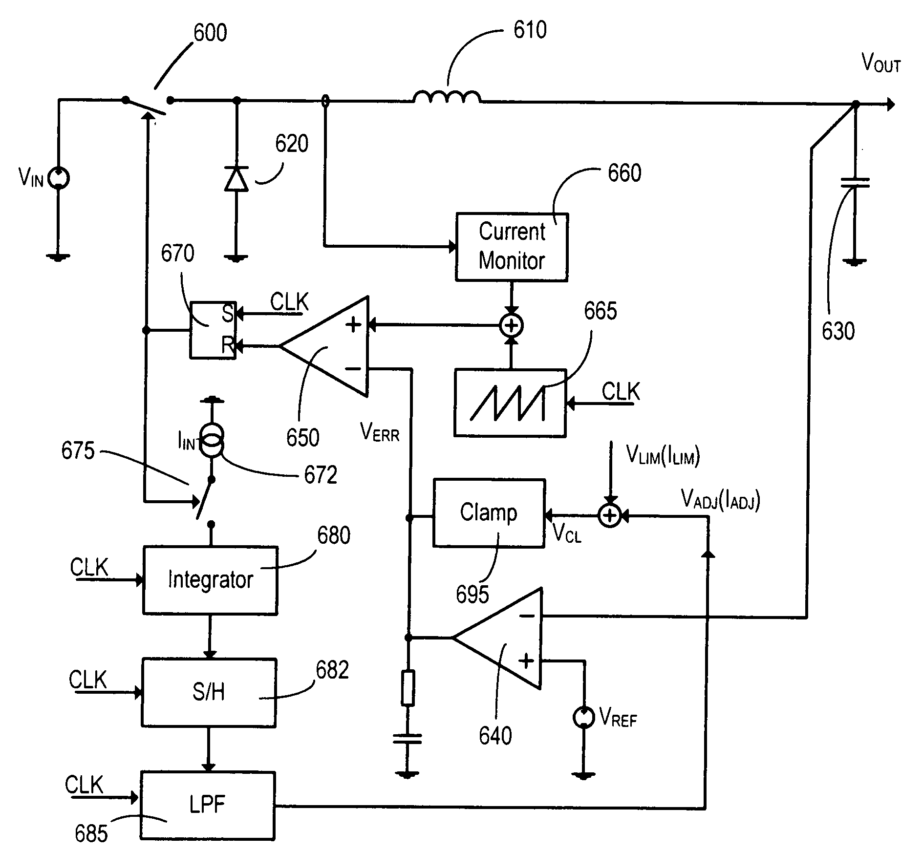
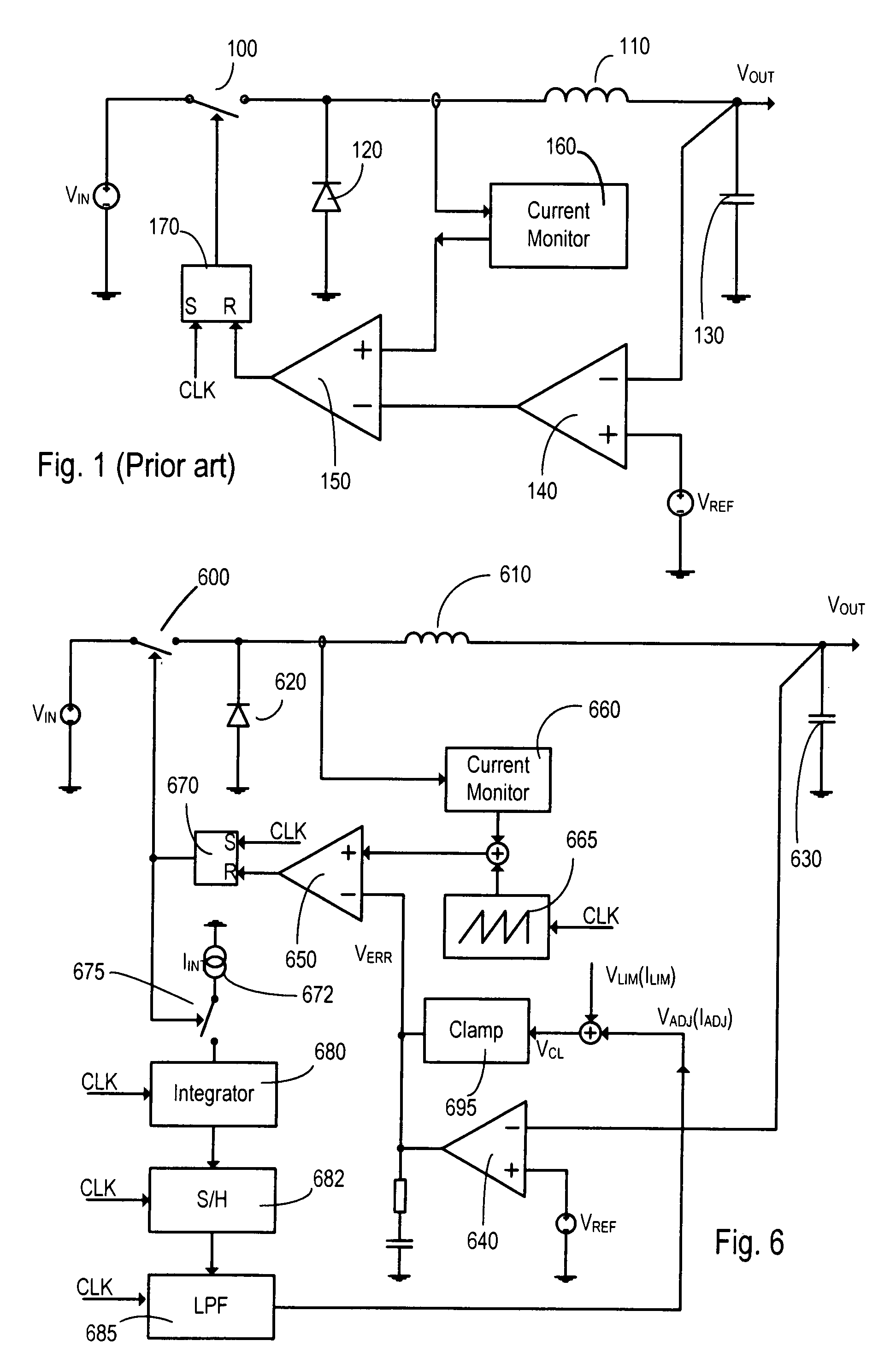
[0048]FIG. 1 shows a block diagram of a basic constant frequency buck converter, although it will be understood that the principles apply equally to any current-mode controlled constant frequency DC-DC converter. The buck converter consists of a power source VIN, a switch 100, an inductor 110, a diode 120 (this could be replaced with a switch running in anti-phase to switch 100), a capacitor 130, an error amplifier 140 (with optional compensating network not shown on this drawing) and reference voltage source VREF, a comparator 150, a current monitor 160 and a latch 170 (with a clock CLK as one input) all connected as shown. In operation, the switch 100 is connected to an input voltage VIN and is closed at the beginning of a clock cycle. Closing the switch causes the current in an inductor 110 connected between the switch 100 and the output VOUT of the converter to rise. This current is monitored by current monitor 160 and is compared by comparator 150 against the output of an error...


PUM


Abstract

A current-mode switching regulator including at least: an inductor; a main switch for controlling the current flow through the inductor; and a feedback control circuit for operating the main switch cyclically and to vary a duty cycle of the main switch so as to substantially maintain an output voltage of the regulator at a desired level. The feedback control circuit further includes slope compensation circuitry adding slope compensation to a signal representing the inductor current prior to the slope compensated signal being compared to the fed-back output error voltage. The regulator further includes current limiting circuitry for controlling the main switch responsive to a current limit reference signal, the current limit circuitry including adjustment circuitry for adjusting the current limit reference signal in response to the duty cycle of more than one previous cycle so as to limit current in the inductor irrespective of the output voltage and to a value which, in the steady state, is substantially independent of the duty cycle.

Description

BACKGROUND OF THE INVENTION[0001]1. Field of the Invention[0002]The present invention relates to switching regulator circuits and in particular to switching regulator circuits which use slope compensation techniques to stabilise the regulator.[0003]2. Description of the Related Art[0004]Switching regulators are very commonly used in DC-DC conversion as they offer higher efficiency than linear regulators. They typically consist, in their most basic form, of an inductor, a capacitor, a diode and a switch which switches the inductor alternately between charging and discharging states. These basic elements can be arranged to form a step-down (buck), step-up (boost) or inverting buck-boost regulator.[0005]Control of the switch has been achieved previously by techniques such as “voltage mode control” and “current-mode control”. In the case of a basic constant frequency current-mode control buck converter the switch is connected to an input voltage and is closed at the beginning of a clock...

Claims


Application Information

Patent Timeline
Patent Type & Authority Applications(United States)
IPC IPC(8): G05F1/00
CPCH02M3/156G05F1/573H02M3/1563H02M3/33507
Inventor DEARN, DAVIDHAIPLIK, HOLGER
Owner CIRRUS LOGIC INC
Why Eureka
Try Eureka