Imaging apparatus

a technology of image sensor and reading section, which is applied in the direction of color signal processing circuit, radiation controlled device, television system, etc., can solve the problems of narrow dynamic range of solid-state image sensor and inability to arrange the reading section of the actual used image sensor, and achieve the effect of suppressing the generation of color mixtures and wide dynamic rang

Inactive Publication Date: 2007-11-29
CANON KK
View PDF5 Cites 25 Cited by
  • Summary
  • Abstract
  • Description
  • Claims
  • Application Information

AI Technical Summary

Benefits of technology

[0007]Exemplary embodiments of the present invention are directed to an imaging apparatus capable of realizing a wide dynamic range while suppressing generation of color mixture.

Problems solved by technology

However, compared to general silver-halide photography, the solid-state image sensor has a narrow dynamic range.
However, a reading section of an actually used image sensor is not arranged to realize the reading mechanism discussed in Japanese Patent Application Laid-Open No. 2003-18471.

Method used


Image

  • Imaging apparatus
  • Imaging apparatus
  • Imaging apparatus

Examples


first exemplary embodiment

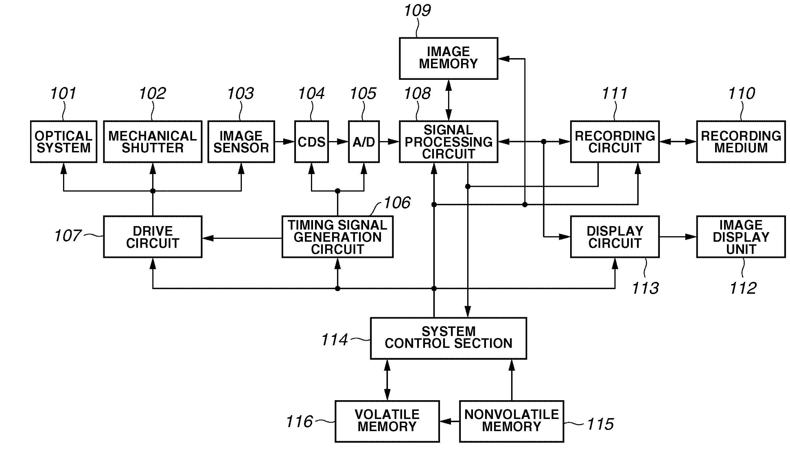
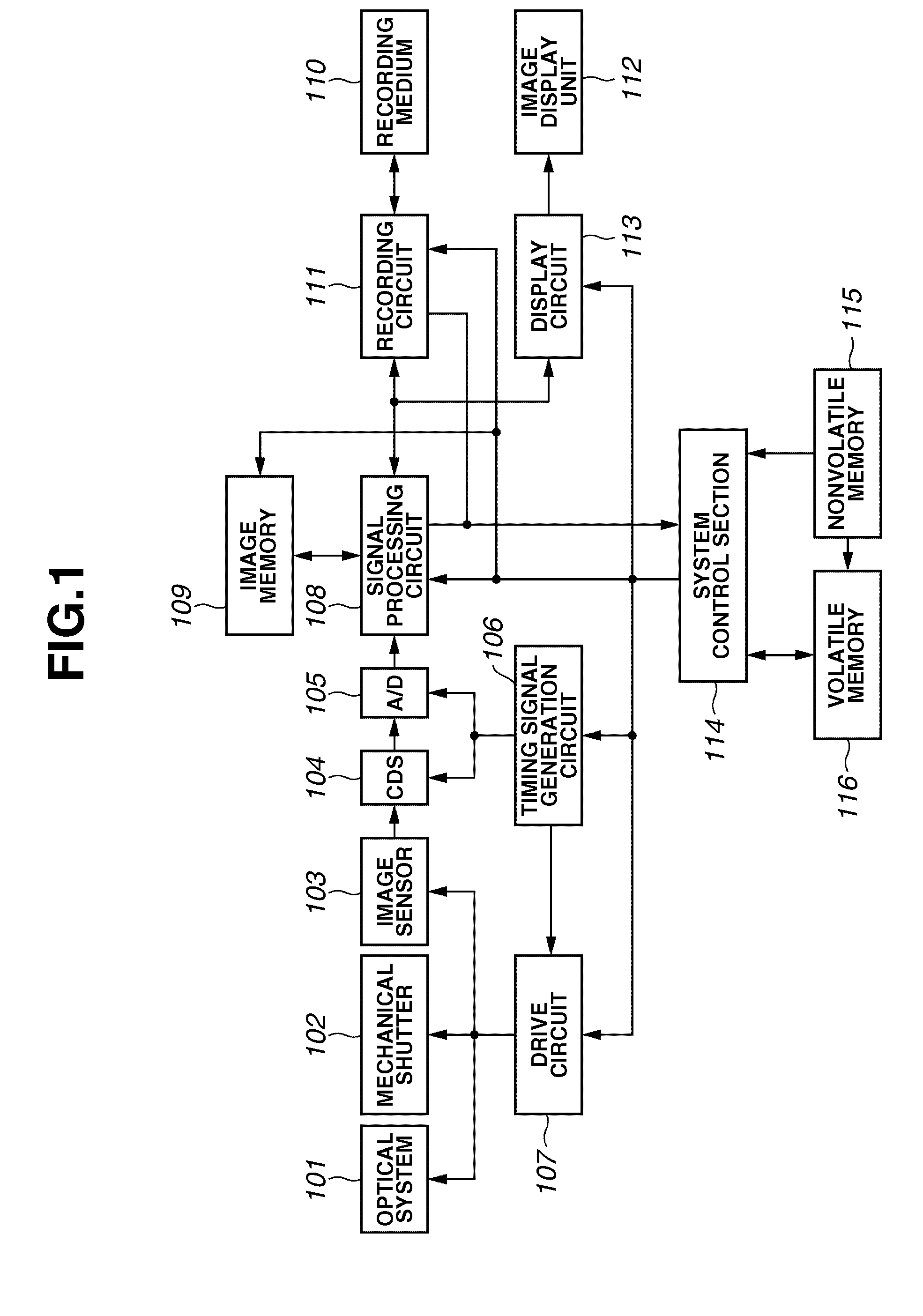
[0032]FIG. 1 is a block diagram illustrating an imaging apparatus according to a first exemplary embodiment of the present invention.

[0033]The imaging apparatus shown in FIG. 1 includes an optical system 101 (e.g., including a lens and a diaphragm), a mechanical shutter 102, an image sensor 103, a correlated double sampling (CDS) circuit 104 performing analog signal processing, and an analog-digital (A / D) converter 105 converting an analog signal to a digital signal. A timing signal generation circuit 106 can generate timing signals to actuate the image sensor 103, the CDS circuit 104, and the A / D converter 105. A drive circuit 107 has a function of driving each of the optical system 101, the mechanical shutter 102, and the image sensor 103.

[0034]Furthermore, the imaging apparatus includes a signal processing circuit 108 applying signal processing to image data captured by the image sensor 103 and an image memory 109 storing the image data processed by the signal processing circuit ...

second exemplary embodiment

[0116]Next, a second exemplary embodiment of the present invention is described. The second exemplary embodiment is different from the first exemplary embodiment in that some of saturation signals overflowing in six directions are neglected depending on the direction of flow. In many cases, a satisfactory processing result can be obtained using only the overflow amounts in an FD of a target pixel and an FD of a neighboring pixel (e.g., the left neighboring pixel in the first exemplary embodiment).

[0117]Hence, the second exemplary embodiment executes image processing considering only two floating diffusion layers positioned at both sides of the saturated photoelectric conversion section. The second exemplary embodiment can speedily accomplish the correction processing.

[0118]The second exemplary embodiment reads the saturated light quantity signal and the photoelectric conversion section signal in a similar manner as in the first exemplary embodiment. FIG. 12 illustrates a color mixtu...

third exemplary embodiment

[0123]Next, a third exemplary embodiment of the present invention is described. The third exemplary embodiment is different from the second exemplary embodiment in that the approximation is further enhanced.

[0124]The approximation used in the third exemplary embodiment is based on a presumption that a neighboring same-color pixel has a same-value signal. In this case, the calculation can be more simplified. The third exemplary embodiment is described based on an image sensor using a Bayer array including a unit matrix of 2×2. FIG. 13 illustrates an exemplary Bayer array which can be expressed by the following formula (12).

a(x−1,y)=a(x+1,y)  (12)

[0125]More specifically, two pixels FD(x−1, y) and FD(x, y) satisfy the following simultaneous linear equations (13). Each of components a(x, y) and a(x−1, y) can be obtained.

FD(x−1,y)=a(x−1,y)+αa(x,y)

FD(x,y)=a(x,y)αa(x−1,y)  (13)

[0126]The approximation used in the third exemplary embodiment requires only a target pixel and a neighboring pix...


PUM


Abstract

An imaging apparatus includes a plurality of pixel portions, each including a photoelectric conversion section and a holding section. The holding section is configured to hold a mixed saturation signal containing a saturation signal overflowing a photoelectric conversion section of the same pixel portion and a saturation signal overflowing a photoelectric conversion section of another pixel portion which functions as a color mixture component. A color mixture correcting section is configured to correct a color mixture component contained in the mixed saturation signal read out of the holding section. A combining section is configured to combine a photoelectric conversion signal read out of the photoelectric conversion section and a corrected saturation signal corrected by the color mixture correcting section.

Description

BACKGROUND OF THE INVENTION[0001]1. Field of the Invention[0002]The present invention relates to an imaging apparatus and a related processing method capable of enlarging a dynamic range while suppressing generation of color mixture.[0003]2. Description of the Related Art[0004]A solid-state image sensor, such as a complementary metal-oxide semiconductor (CMOS), can be used in a digital camera or other imaging apparatuses. However, compared to general silver-halide photography, the solid-state image sensor has a narrow dynamic range. To solve this drawback, there are various dynamic range enlarging methods (refer to Japanese Patent Application Laid-Open No. 2003-18471).[0005]For example, according to an image sensor discussed in Japanese Patent Application Laid-Open No. 2003-18471, saturated charge overflows a photoelectric conversion section and flows into a reading section if a light quantity of incident light exceeds a saturation light quantity of the photoelectric conversion sect...

Claims


Application Information

Patent Timeline
Patent Type & Authority Applications(United States)
IPC IPC(8): H04N9/73H01L27/146H04N5/335H04N5/355H04N5/357H04N5/369H04N5/374H04N9/07
CPCH04N9/045H04N23/84H04N25/134
Inventor SHIRAI, KUNIHIRO
Owner CANON KK
Why Eureka
Try Eureka