Physical quantity sensor having spring
a technology of physical quantity and sensor, which is applied in the direction of speed/acceleration/shock measurement, measurement devices, instruments, etc., can solve the problems of low linearity of the relationship between the sensor and the external environment, incompatibility between the wide dynamic range of the acceleration, so as to achieve wide dynamic range of acceleration and small size , the effect of wide detection rang
- Summary
- Abstract
- Description
- Claims
- Application Information
AI Technical Summary
Benefits of technology
Problems solved by technology
Method used
Image
Examples
first embodiment
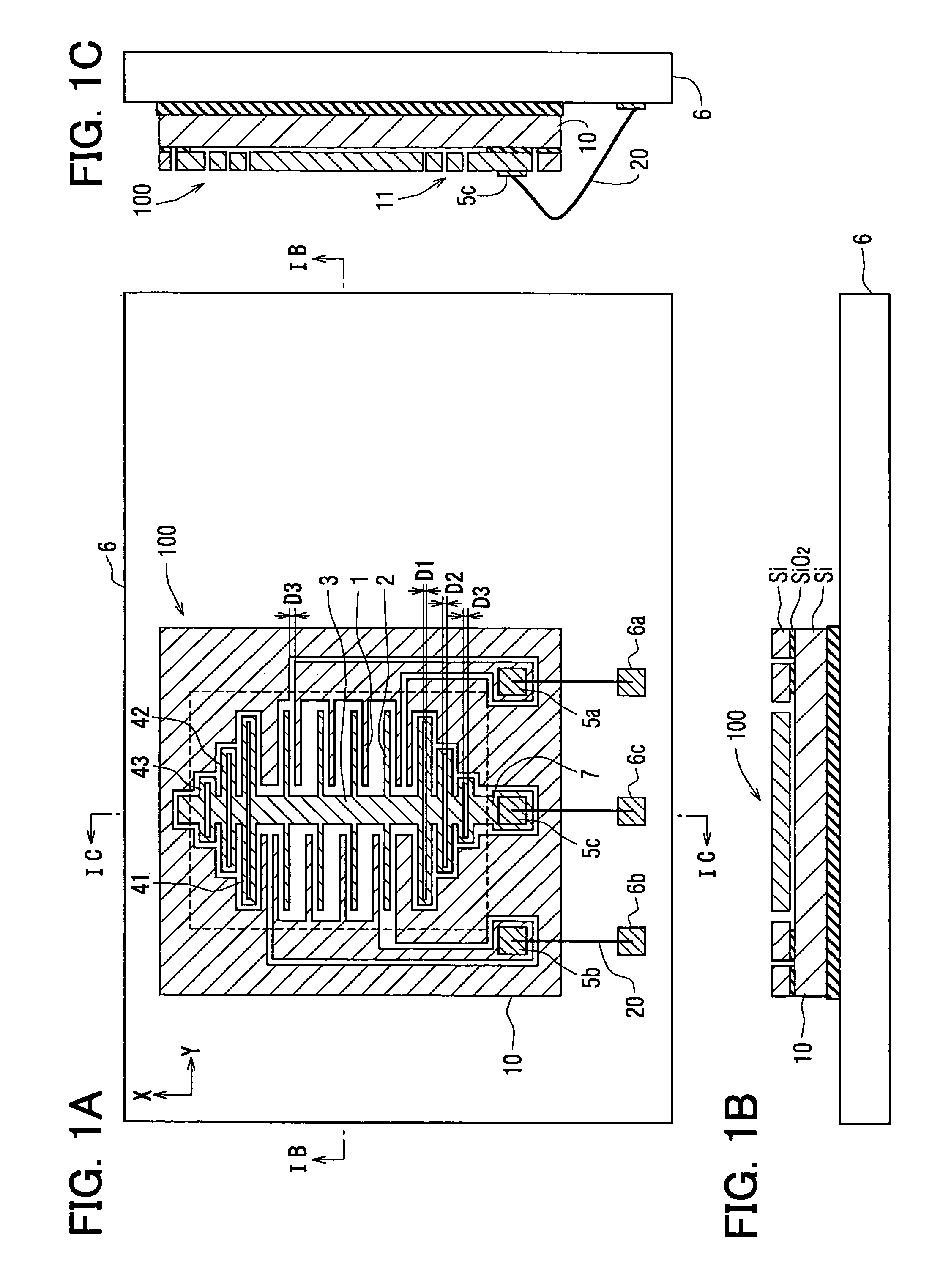
[0028]The inventors preliminarily manufactured a physical quantity sensor as a comparison. The sensor is a capacitance type acceleration sensor 101 shown in FIGS. 3A-3C. The sensor 101 detects acceleration in X-axis, i.e., the sensor 101 detects single directional acceleration. The sensor 101 includes a semiconductor substrate 10 made of silicon and the like. The substrate 10 has multiple grooves 11 for providing multiple pairs of fixed electrodes 1 and movable electrodes 2. A pair of the fixed electrode 1 and the movable electrode 2 faces each other in the X direction so that it forms a capacitor having a capacitance. A massive portion 3 extends to the X direction. The movable electrodes 2 protrude from the massive portion 3 in a Y direction so that the movable electrodes 2 have a comb-teeth shape. The massive portion 3 has two ends, both of which connect to the substrate 10 so that the massive portion 3 is displaceable (i.e., movable) in the X direction. Both ends of the massive p...
second embodiment
[0041]The inventors preliminarily manufactured a physical quantity sensor as another comparison. The sensor is a capacitance type acceleration sensor 201 shown in FIG. 10. The sensor 201 includes a substrate having multiple grooves so that the fixed electrode 1 and the movable electrodes 2 are formed. The fixed electrode 1 includes a right side fixed electrode 1c and a left side fixed electrode 1d. The right side and left side fixed electrodes 1c, 1d face the movable electrode 2 in the X direction, which is a detection direction of the acceleration so that capacitors having a capacitance are formed, respectively.
[0042]The massive portion 3 extends to the X direction. The movable electrodes 2 protrude from the massive portion 3 in the Y direction so that the movable electrodes 2 have a comb-teeth shape. The massive portion 3 has two ends, both of which connect to the substrate 10 so that the massive portion 3 is displaceable (i.e., movable) in the X direction. Both ends of the massiv...
third embodiment
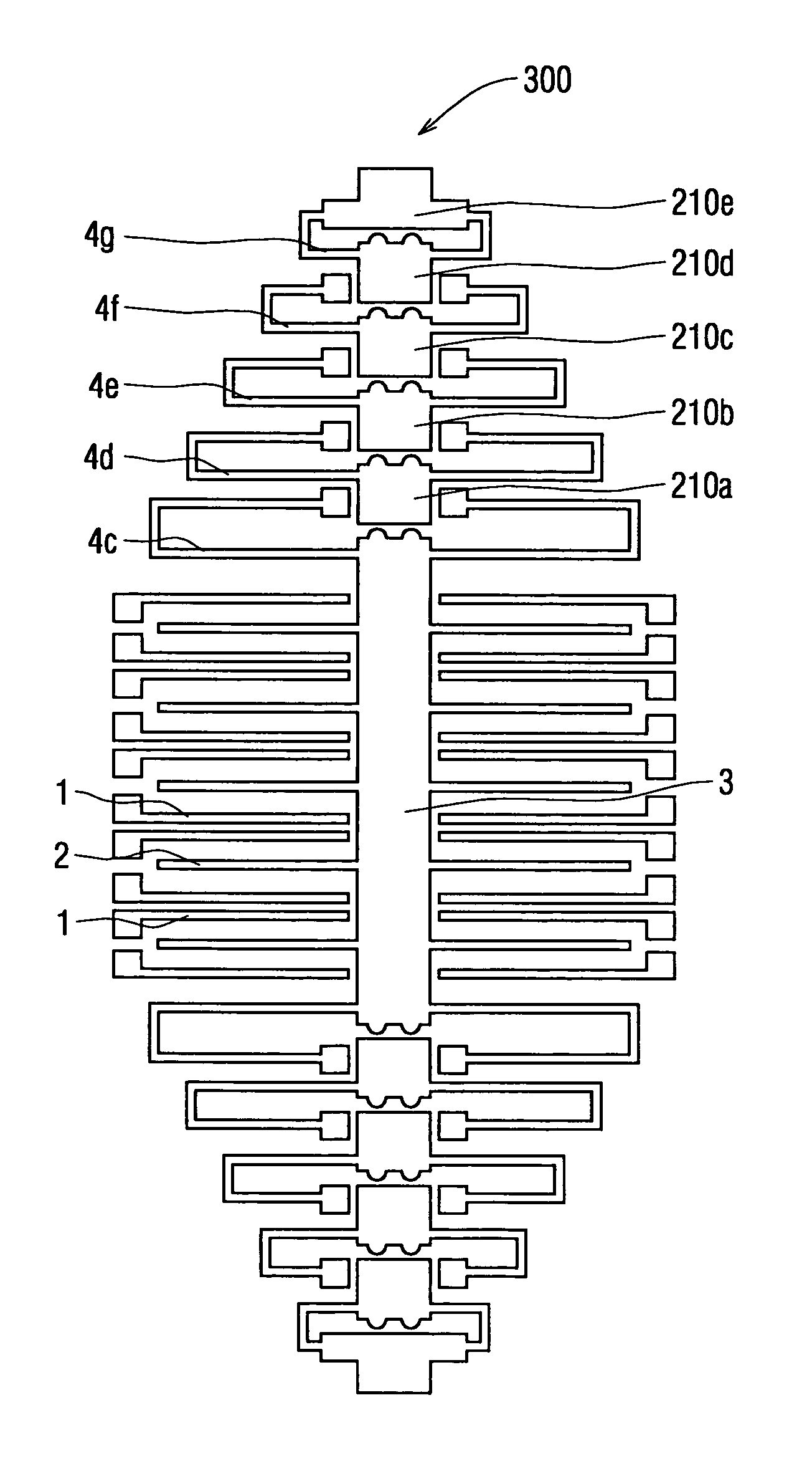
[0053]A physical quantity sensor 300 according to a third embodiment of the present invention is shown in FIG. 7. The sensor 300 includes multiple springs 4c-4g and multiple stoppers 210a-210e. In FIG. 7, five springs 4c-4g and five stoppers 210a-210e are disposed on both ends of the massive portion 3. The five springs 4c-4g have different spring constants, respectively.
[0054]The first stopper 210a for limiting the first spring 4c is supported on the second spring 4d. The first spring 4c has a latitudinal length longer than that of the second spring 4d so that the spring constant of the first spring 4c is smaller than that of the second spring 4d. The second stopper 210b for limiting the second spring 4d is supported on the third spring 4e. The second spring 4d has a latitudinal length longer than that of the third spring 4e so that the spring constant of the second spring 4d is smaller than that of the third spring 4e. The third stopper 210c for limiting the third spring 4e is supp...
PUM
 Abstract
Description
Claims
Application Information
 - R&D
- Intellectual Property
- Life Sciences
- Materials
- Tech Scout
- Unparalleled Data Quality
- Higher Quality Content
- 60% Fewer Hallucinations
Browse by: Latest US Patents, China's latest patents, Technical Efficacy Thesaurus, Application Domain, Technology Topic, Popular Technical Reports.
© 2025 PatSnap. All rights reserved.Legal|Privacy policy|Modern Slavery Act Transparency Statement|Sitemap|About US| Contact US: help@patsnap.com


