Image obtaining apparatus, image synthesis method and microscope system

a technology of image synthesis and microscope system, applied in the field of image processing techniques, can solve the problems of limited generation frame rate of wide dynamic range image, dark area of subject may suffer “blackout”, and may emerge, and achieve the effect of wide dynamic rang

Inactive Publication Date: 2010-11-25
OLYMPUS CORP
View PDF22 Cites 24 Cited by
  • Summary
  • Abstract
  • Description
  • Claims
  • Application Information

AI Technical Summary

Benefits of technology

[0012]A microscope system being yet another aspect of the present invention includes a microscope obtaining a microscopic image of a sample; and an image obtaining apparatus obtaining a picture of the microscopic image, and the image obtaining apparatus includes: an image sensor capturing the microscopic image being an observation image formed on a light-receiving surface; an original entire-area image capturing control unit controlling the image sensor under a first exposure condition to make the image sensor capture an original entire-area image being a picture of the observation image for an entire area of the light-receiving surface; a partial-area image capturing control unit controlling the image sensor under a second exposure condition being different from the first exposure condition to make the image sensor capture a partial-area image being a picture of the observation image for only a partial area of the light-receiving surface; and a synthesizing unit synthesizing the original entire-area image and the partial-area image to obtain an entire-area image having a wider dynamic range than the original entire-area image.

Problems solved by technology

For this reason, a problem may emerge in camera shooting in a scene with strong contrast (shooting with backlight or indoor and outdoor simultaneous shooting) or in capturing images for observing industrial samples (such as an IC chip and an electronic substrate) related to microscopic measurement.
On the other hand, when an observation image of the subject is captured with the exposure time adjusted to a value that is appropriate for the light area of the subject, the dark area of the subject may suffer “black out”.
For this reason, the generation frame rate for the wide dynamic range image is limited by the time required for obtaining images with the entire area in both image capturing with the long exposure time and image capturing with the short exposure time.

Method used


Image

  • Image obtaining apparatus, image synthesis method and microscope system
  • Image obtaining apparatus, image synthesis method and microscope system
  • Image obtaining apparatus, image synthesis method and microscope system

Examples


Embodiment Construction

[0031]Hereinafter, embodiments of the present invention are explained in accordance with drawings.

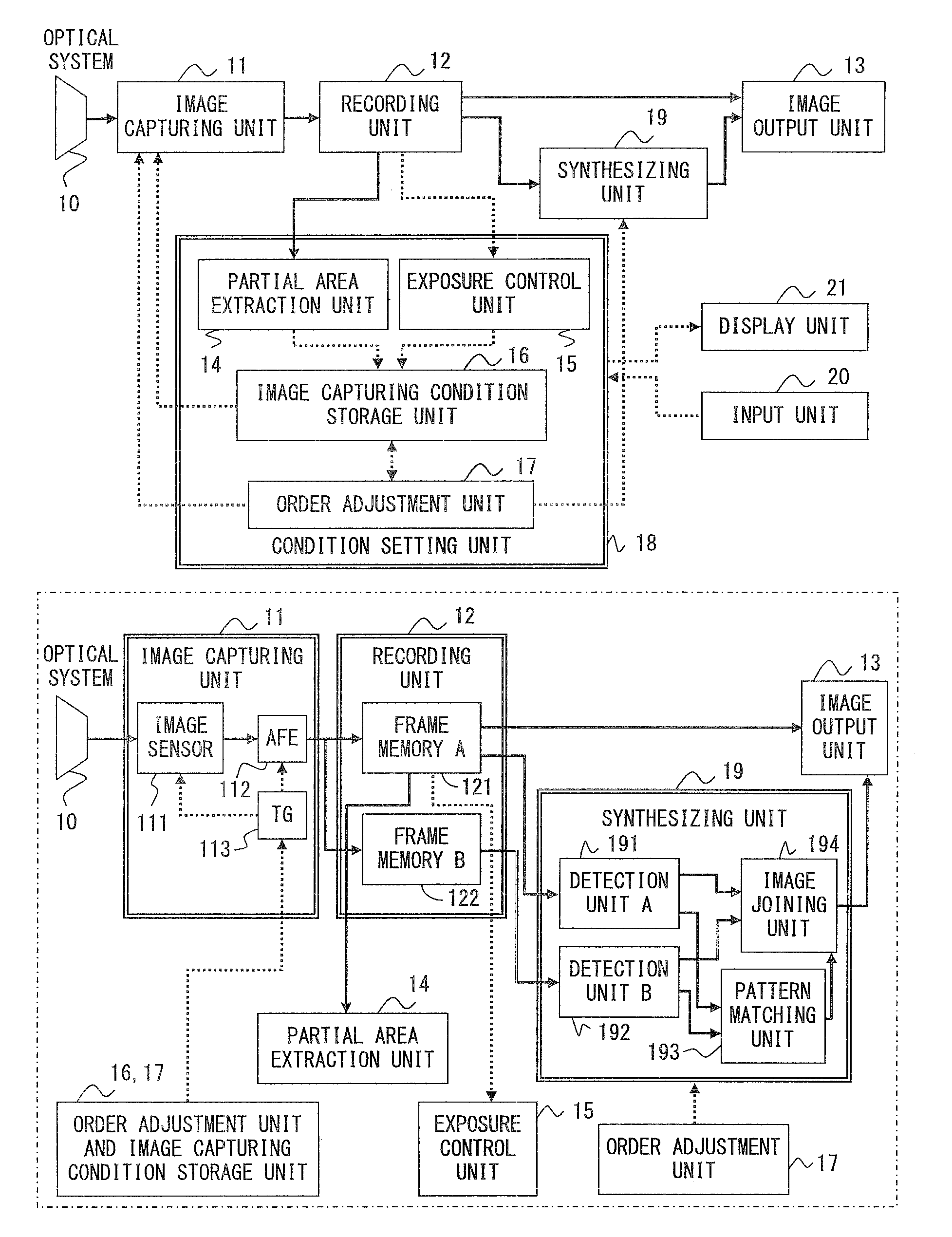
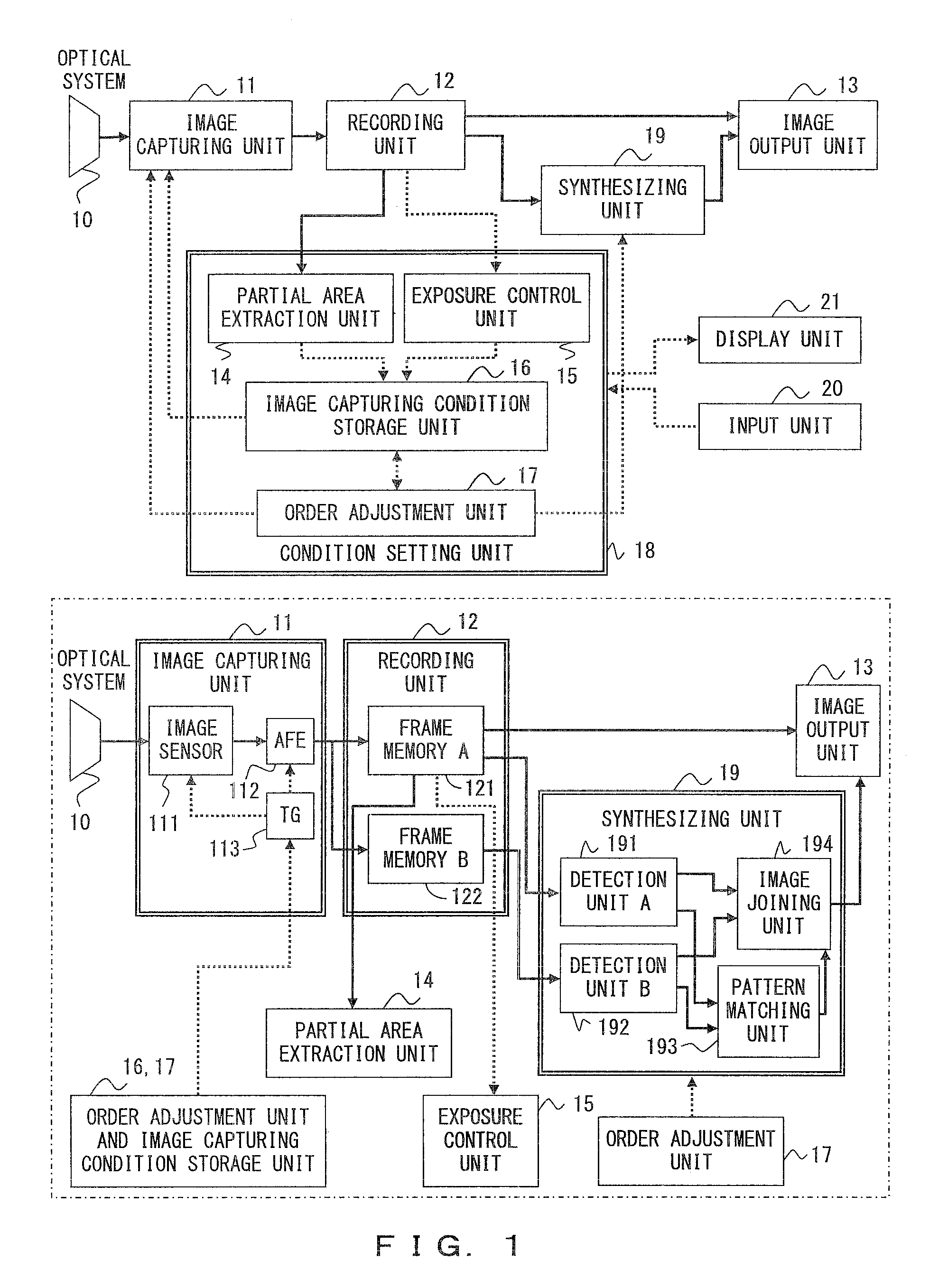
[0032]FIG. 1 is explained first. FIG. 1 illustrates a first example of the configuration of the image capturing apparatus for a microscope that is an image obtaining apparatus with which the present invention is implemented.

[0033]This image capturing apparatus for a microscope (hereinafter referred to as “the image capturing apparatus”) captures one of a long-time exposure image and a short-time exposure image used for the generation of a wide dynamic range image, as an image (hereinafter, referred to as an “original entire-area image”) captured with the entire area of the light-receiving surface of the image sensor, and captures the other of a long-time exposure image and a short-time exposure image as an image (hereinafter, referred to as a “partial-area image”) obtained by capturing an observation image in a partial area of the light-receiving surface of the image sensor. The generat...


PUM


Abstract

An image sensor captures an observation image formed on a light-receiving surface. An order adjustment unit makes the image sensor capture an original entire-area image being a picture of the observation image for an entire area of the light-receiving surface under a first exposure condition, and makes the image sensor capture a partial-area image being a picture of the observation image for only a partial area of the light-receiving surface under a second exposure condition. A synthesizing unit synthesizes the original entire-area image and the partial-area image to obtain an entire-area image having a wider dynamic range than the original entire-area image.

Description

CROSS-REFERENCE TO RELATED APPLICATIONS[0001]This application claims benefit of Japanese Application No. 2009-125859, filed May 25, 2009, the contents of which are incorporated by this reference.BACKGROUND OF THE INVENTION[0002]1. Field of the Invention[0003]The present invention relates to image processing techniques, especially a technique for obtaining a high-quality image from a plurality of captured images.[0004]2. Description of the Related Art[0005]Currently, image capturing apparatuses are generally configured to have image sensors using a CCD (Charge Coupled Device), CMOS (Complementary Metal Oxide Semiconductor), and the like. Such image sensors have a narrower dynamic range for contrast, compared with that of photographic films and human vision. For this reason, a problem may emerge in camera shooting in a scene with strong contrast (shooting with backlight or indoor and outdoor simultaneous shooting) or in capturing images for observing industrial samples (such as an IC ...

Claims


Application Information

Patent Timeline
Patent Type & Authority Applications(United States)
IPC IPC(8): H04N7/18H04N5/235
CPCG06T5/008G06T5/50G06T2207/10056G06T2207/20104H04N5/2355G06T2207/20221G06T2207/30148H04N5/235G06T2207/20208H04N23/70H04N23/741
Inventor YOKOMACHI, YUKIARAI, YUJIN
Owner OLYMPUS CORP
Why Eureka
Try Eureka