Optical navigation sensor with tracking and lift detection for optically transparent contact surfaces

a technology of optical transparency and optical navigation, applied in the direction of instruments, computing, electric digital data processing, etc., can solve problems such as the mouse from tracking

Inactive Publication Date: 2007-12-20
MONTEREY RES LLC
View PDF12 Cites 38 Cited by
  • Summary
  • Abstract
  • Description
  • Claims
  • Application Information

AI Technical Summary

Problems solved by technology

However, the relatively small lift margin may prevent the mouse from tracking on an optically transparent tracking surface, such a...

Method used


Image

  • Optical navigation sensor with tracking and lift detection for optically transparent contact surfaces
  • Optical navigation sensor with tracking and lift detection for optically transparent contact surfaces
  • Optical navigation sensor with tracking and lift detection for optically transparent contact surfaces

Examples


Embodiment Construction

[0019]In the present disclosure, numerous specific details are provided, such as examples of apparatus, components, and methods, to provide a thorough understanding of embodiments of the invention. Persons of ordinary skill in the art will recognize, however, that the invention can be practiced without one or more of the specific details. In other instances, well-known details are not shown or described to avoid obscuring aspects of the invention.

[0020]Embodiments of the present invention are disclosed using computer optical mice as examples. It should be understood, however, that the present teachings are equally applicable to other optical navigation sensors, particularly those used as pointing devices in computer systems.

[0021]The present disclosure includes lift detection techniques. Commonly-assigned U.S. Provisional Application No. 60 / 623,320, filed on Oct. 29, 2004 and U.S. application Ser. No. 11 / 244,650, filed on Oct. 5, 2005 also pertain to lift detection.

[0022]Lift detect...


PUM


Abstract

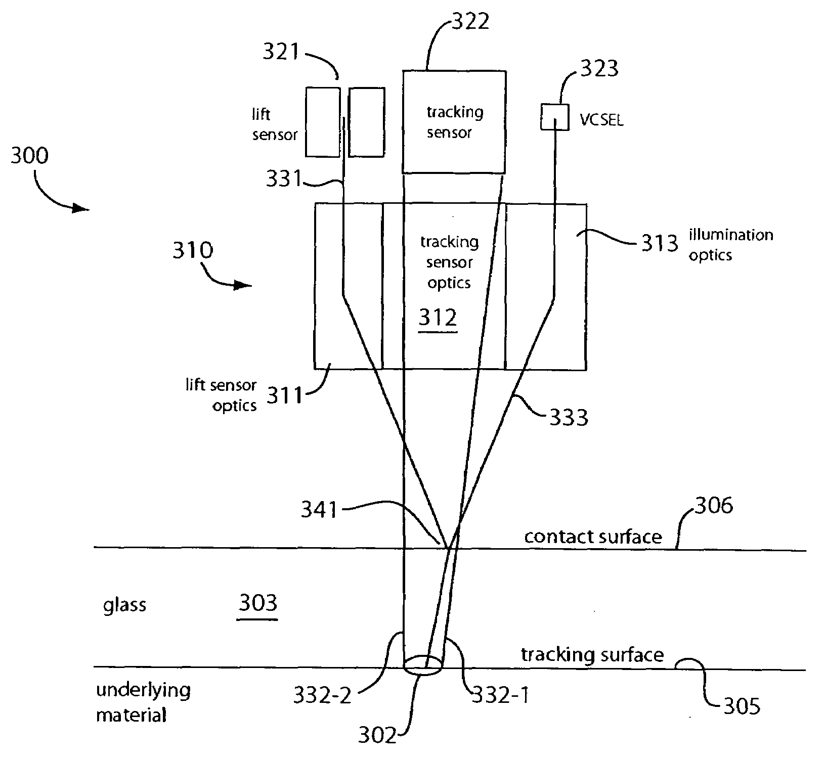
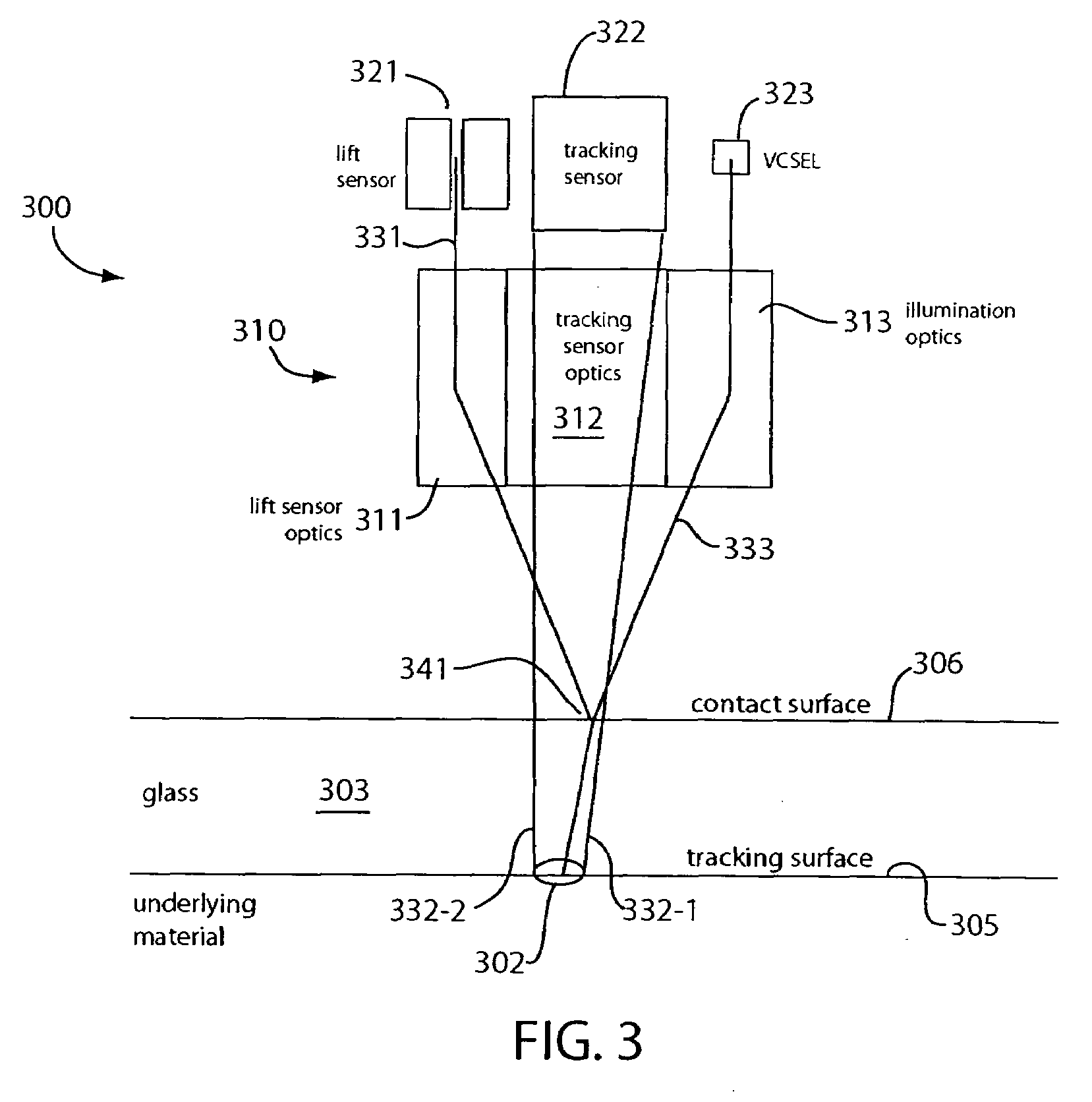
In one embodiment, an optical navigation sensor for a computer mouse is designed to be operable on an optically transparent material. The optically transparent material may include a contact surface on which the mouse sits during normal operation. An optically rough tracking surface is provided below the contact surface. The mouse includes a light source that illuminates an area on the contact surface and an area on the tracking surface. The mouse may include a tracking sensor onto which the illuminated area on the tracking surface is imaged to detect mouse displacement. The mouse may also include a lift sensor that picks up specular light reflected from the illuminated area on the contact surface to generate lift information indicative of whether the mouse has been lifted off the contact surface. Tracking of the mouse displacement may be qualified with the lift information.

Description

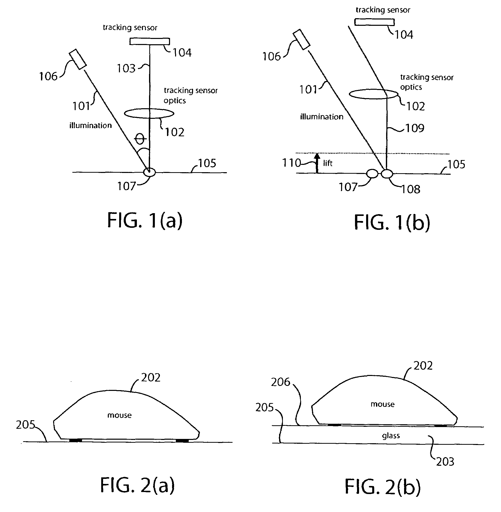
BACKGROUND OF THE INVENTION[0001]1. Field of the Invention[0002]The present invention relates generally to optical navigation sensors, and more particularly to optical pointing devices used in computer systems.[0003]2. Description of the Background Art[0004]A computer mouse is an example of a two-dimensional navigation sensor. As employed with a personal computer, a mouse has an associated cursor displayed on-screen; the cursor moves relative to the mouse's movement. Some mice employ optical, rather than mechanical, technology to track movement. A conventional optical mouse includes a light source that illuminates an optically rough tracking surface at an oblique incident angle. The illuminated portion of the tracking surface is imaged to a tracking sensor, such as a CCD, CMOS imaging array, 2D comb array, etc. A tracking algorithm implemented in the mouse controller analyzes successive captured images or signals to determine mouse displacement along the tracking surface.[0005]Conve...

Claims


Application Information

Patent Timeline
IPC IPC(8): G09G5/08
CPCG06F3/0317
Inventor TRISNADI, JAHJA I.CARLISLE, CLINTON B.XU, YANSUN
Owner MONTEREY RES LLC
Why Eureka
Try Eureka