

Compressive coupling of an implantable hearing aid actuator to an auditory component
- Summary
- Abstract
- Description
- Claims
- Application Information
AI Technical Summary
Benefits of technology
Problems solved by technology
Method used
Image

Examples
first embodiment
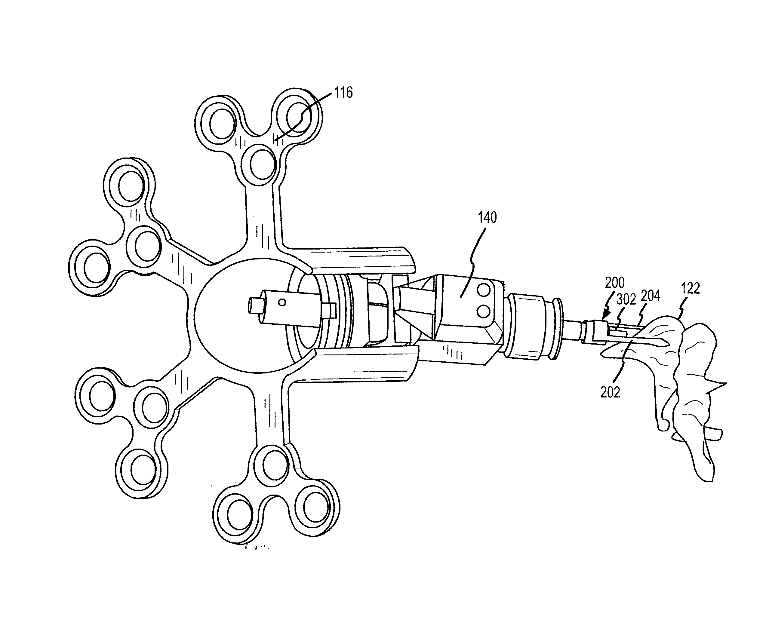
[0053]FIGS. 3-5 show a connection apparatus formed as a guide assembly 200 that may be utilized with a transducer vibratory actuator tip 302 (e.g., see FIG. 4). As shown, the guide assembly 200 includes first and second guide armatures 202, 204 and an interconnecting member 206 that extends between the guide armatures 202, 204. The guide armatures are sized to, when connected to the transducer 140, extend beyond the transducer vibratory actuator tip 302. The connecting member 206 is curved to match the curvature of the outside surface of the vibratory actuator of the transducer 140 for co-movement therewith. In this regard, the guide assembly 200 may be attached to a curved outside surface of a vibratory component of the transducer 140. In another arrangement, the guide assembly 200 is interconnected to a stationary portion of the transducer 140. That is, the guide assembly 200 does not move with movement of the transducer tip 302 the transducer 140.
[0054] As shown in FIGS. 4 and 5,...
second embodiment
[0055]FIG. 6 illustrates a guide assembly 240 that may be utilized to align a transducer vibratory actuator tip 302 relative to an auditory component. In this embodiment, a cap 242 is sized to fit over an end of the transducer 140. The end of the cap (not shown) is open to permit the movable tip 302 to extend therethrough. Alternately, the tip 302 may be attached to the end of the cap 242. The cap member 242 may be affixed to the transducer 140 in any appropriate manner including, without limitation, in a snap-fit arrangement, by welding and / or by adherence. Interconnected to opposing outside surfaces of the cap member 242 are first and second guide wires 244, 246. These guide wires 244, 246 extend toward and beyond the vibratory actuator tip 302 of the transducer 140. These guide wires 244, 246 are spaced to engage opposing surfaces of an ossicle bone such as the incus 122. In the present embodiment, the guide wires 244, 246 are bent to conform to the outside surface of the incus 1...
PUM
 Abstract
Description
Claims
Application Information