System for docking a movable platform

Active Publication Date: 2015-11-05
OPIFLEX AUTOMATION
View PDF5 Cites 0 Cited by
  • Summary
  • Abstract
  • Description
  • Claims
  • Application Information

AI Technical Summary

Benefits of technology

[0025]If there is a low friction between the guiding surface and the positioning portion, the angle α2 of the guiding surface can be larger than when there is a high friction between the guiding surface and the positioning portion.
[0026]According to a further embodiment of the invention, the recess is rotationally symmetric and a radial distance between an upper periphery of the guiding surface and a lower periphery of the support surface is more than 5 mm. To improve the docking procedure the protruding member needs to be fitted into the recesses in a fast and efficient manner. If the distance is too small, more time is needed to position the protruding member above the recess before guiding the protruding member towards the space.
[0027]According to an embodiment of the invention, the recess, the bearing portion, and the positioning portion are rotationally symmetric. If the recess is symmetric in relation to the center axis, this will further facilitate the

Problems solved by technology

It is usually not economically feasible to install a robotic device at each working machine if the working machine has low utilization or the batch sizes a

Method used


Image

  • System for docking a movable platform
  • System for docking a movable platform
  • System for docking a movable platform

Examples


Example

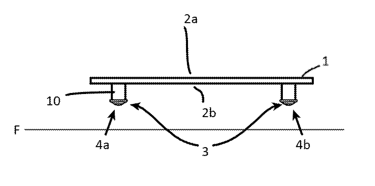
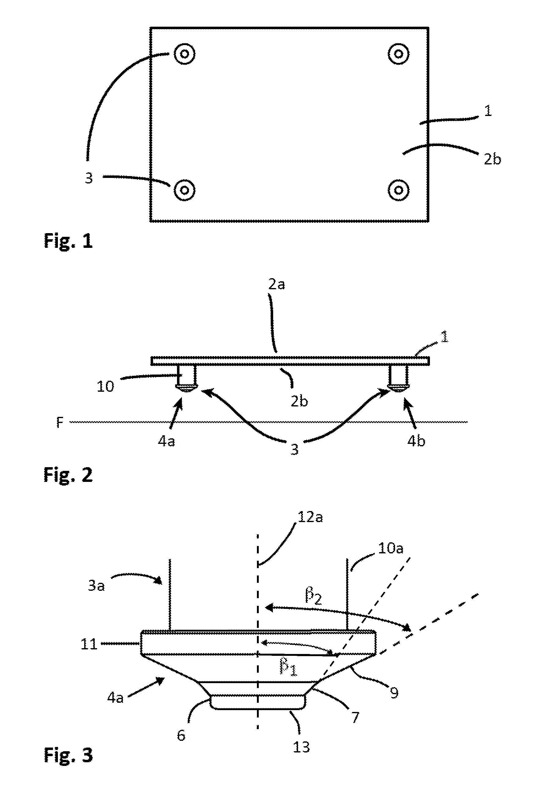
[0046]FIGS. 1 and 2 shows an example of a movable platform 1. FIG. 1 shows a view from below of the platform and FIG. 2 shows a side view of the platform. The movable platform 1 has a top surface 2a and a bottom surface 2b. The surfaces extend along a horizontal plane parallel to a floor F. A plurality of protruding members 3 protrude from the bottom surface of the platform and may be designed as legs supporting the platform. The platform may have two, three or more legs. In this embodiment, the platform is provided with four legs to support the platform. The protruding members 3 may be fixedly attached to the platform. The protruding members 3 may also be linearly movable relative to the platform. The platform may also be provided with wheels. The wheels can be fixed in order to support the platform, or movable relative to the platform.

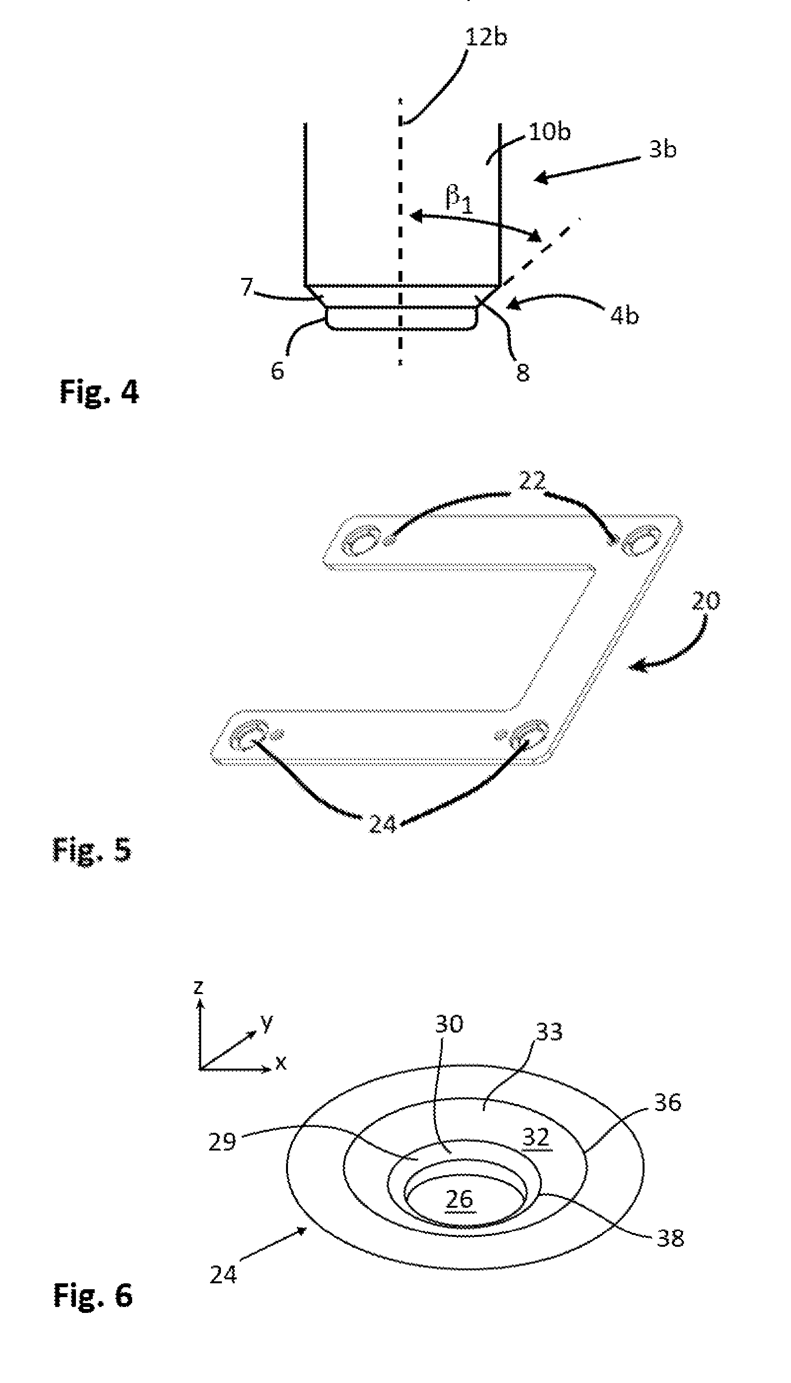
[0047]FIGS. 3 and 4 show two examples of protruding members 3a and 3b. The protruding members 3a-b extend along a central axis 12a, 12b. An outer en...


PUM

PropertyMeasurementUnit
Angleaaaaaaaaaa
Angleaaaaaaaaaa
Angleaaaaaaaaaa

Abstract

The present invention relates to a system for docking a platform (1) adapted to carry a manipulator (42), in relation to a workstation. The system comprises a plurality of protruding members attached to the platform, a docking station to be arranged at the workstation and comprising a plurality of recesses adapted to receive the protruding members and by that positioning the platform relative the workstation. Each of the recesses comprises a positioning section (26) defining a space and a supporting section tapering towards the positioning section and having at least one support surface (30), and the protruding members are protruding away from a bottom surface of the platform, and an outer end of each of the protruding members comprises a positioning portion (6) designed to at least partly fit in said space, and a bearing portion (7) tapering towards the positioning portion and having a bearing surface (8), and the bearing surface is adapted to bear on the support surface when the positioning portion is fitted in said space. The positioning section (26) and the positioning portion (6) are designed so that an accommodation (40) for collecting dust and dirt is formed below the positioning portion when the positioning portion is fitted in said space.

Description

FIELD OF THE INVENTION[0001]The present invention relates to a system for docking a movable platform adapted to carry a manipulator, in relation to a workstation. The invention also relates to the use of the docking system.BACKGROUND OF THE INVENTION AND PRIOR ART[0002]In many small factories the manufacturing takes place at different workstations containing one or several fixed machines. Manipulators, such as a robot, tending the machines or performing work tasks can be used in order to increase productivity, cost efficiency, quality or remove monotonous and hazardous work tasks. It is usually not economically feasible to install a robotic device at each working machine if the working machine has low utilization or the batch sizes are small. For small batch sizes, manual operation of the machines is wanted. Therefore, there is a need to easily move a robot unit between different workstations to obtain an optimal use of the robot and get easy manual access to the machines.[0003]To i...

Claims


Application Information

Patent Timeline
IPC IPC(8): B25J9/10G05D1/02
CPCY10T403/7039B25J9/10B23Q1/0063B25J5/00Y10T403/33Y10T29/49899Y10T24/45262F16B2200/10B25J5/007G05D1/02F16B5/0056F16B5/065F16B5/0088
Inventor FRISK, JOHAN
Owner OPIFLEX AUTOMATION
Why Eureka
Try Eureka