

Sensor-type flushing system for a toilet tank
- Summary
- Abstract
- Description
- Claims
- Application Information
AI Technical Summary
Problems solved by technology
Method used
Image

Examples
Embodiment Construction
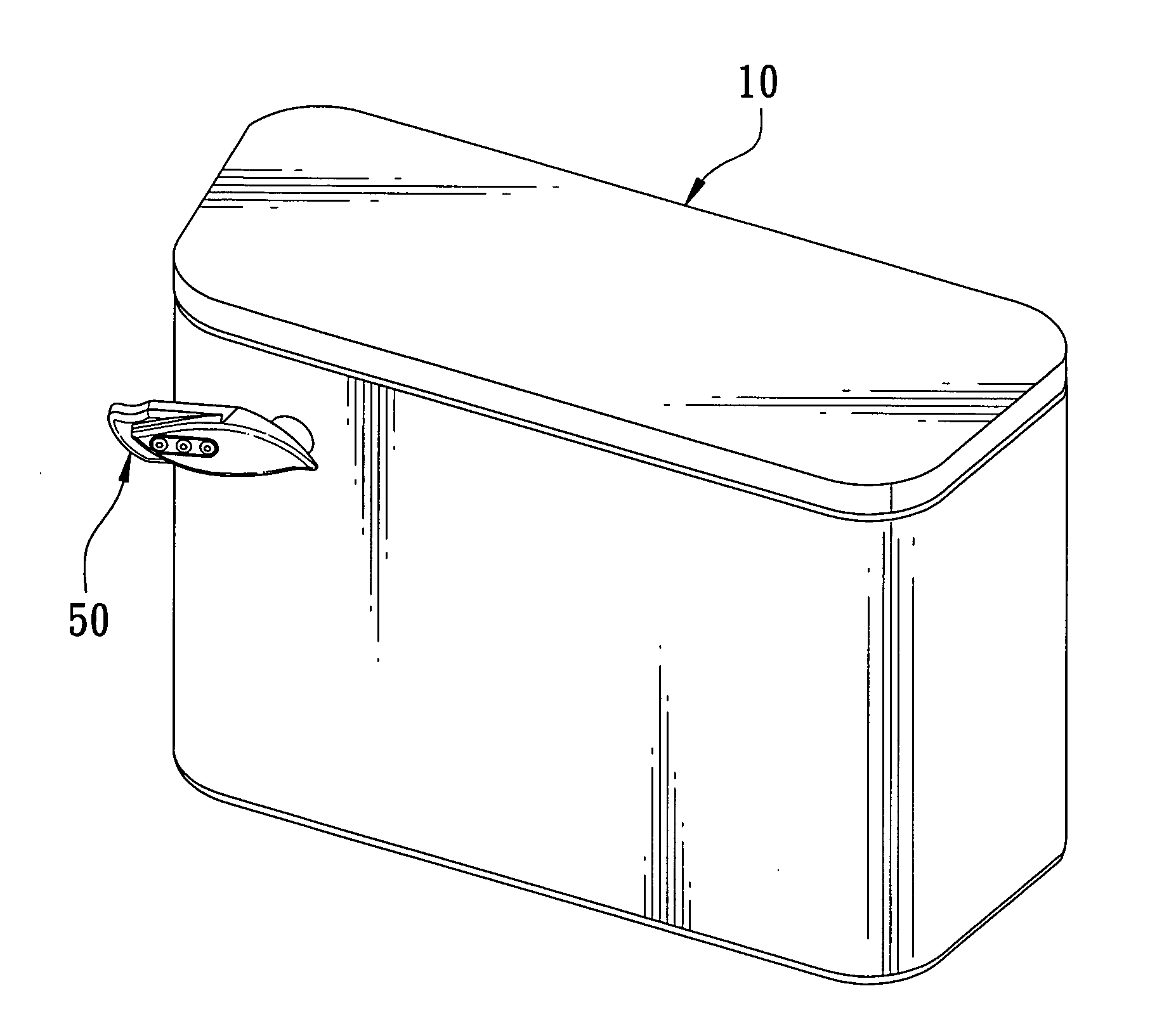
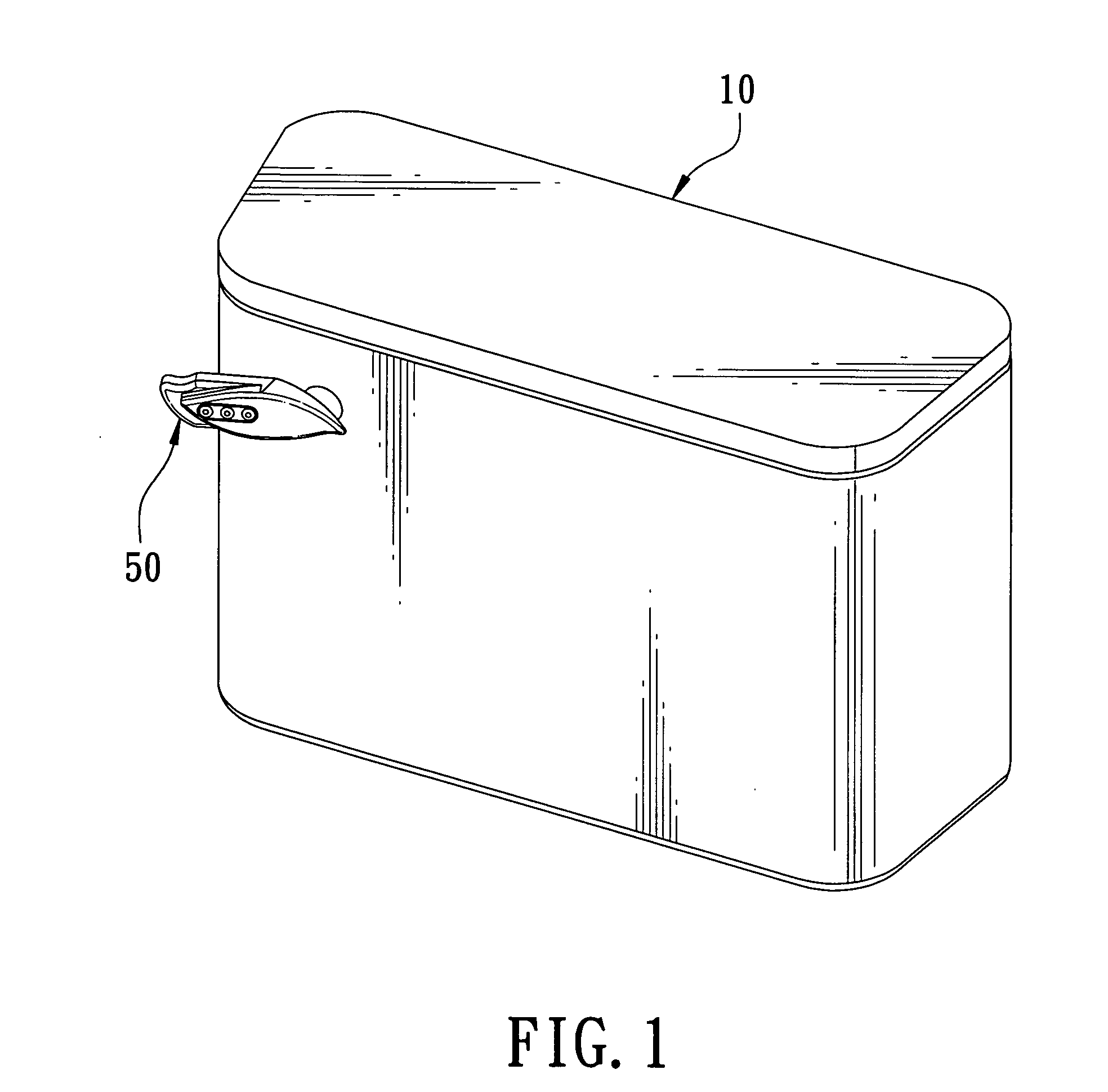
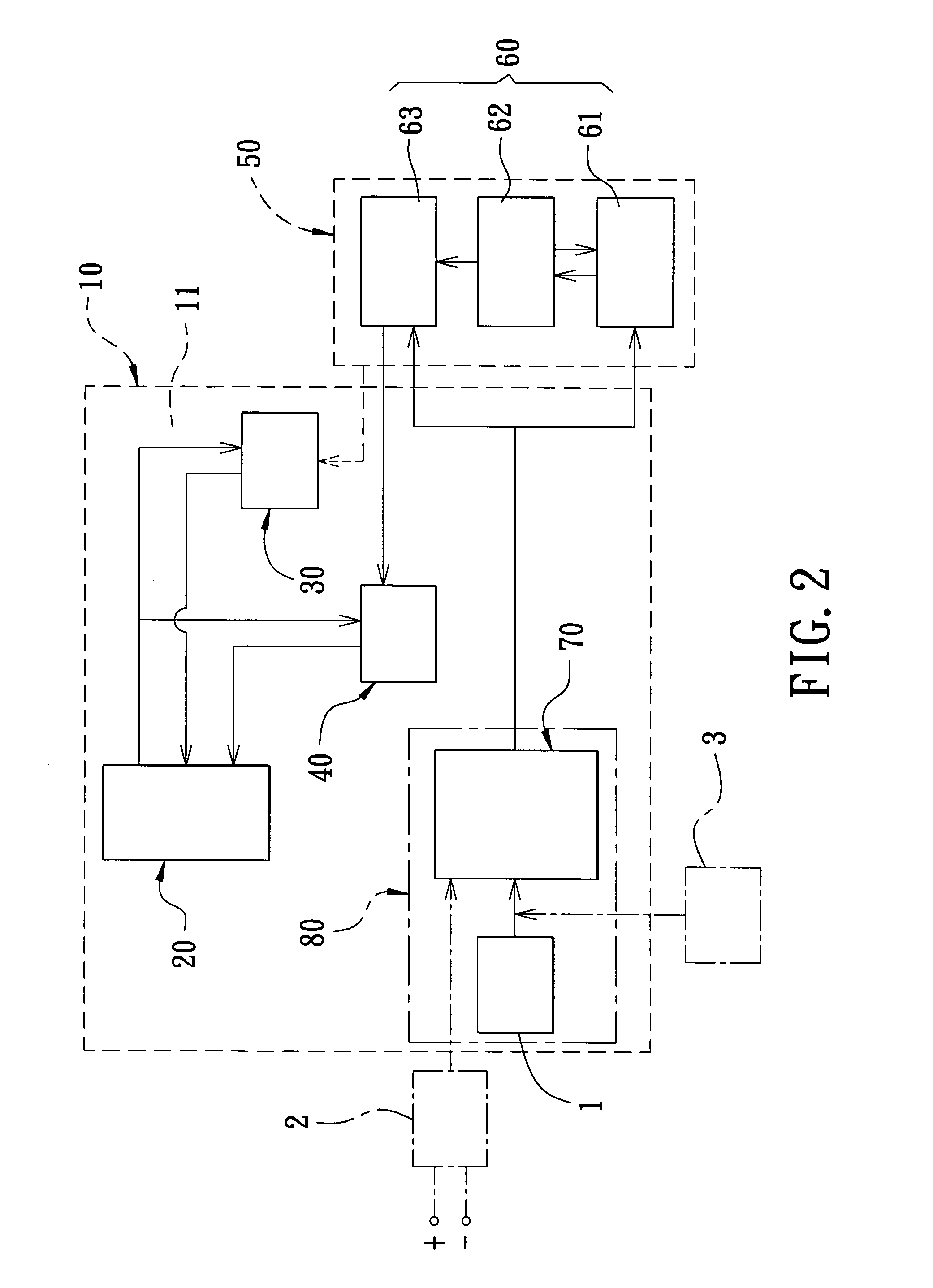
[0023]A preferred embodiment of a sensor-type flushing system for a toilet tank in the present invention, as shown in FIGS. 1, 2 and 3, includes a toilet tank 10, a pressured tank 20, a switch valve 30, an electromagnetic valve 40, an operational device 50, a sensor 60, a power circuit 70 and a control case 80 as main components.
[0024]The toilet tank 10 shown in FIG. 3 is made of porcelain, provided with a hollow space 11 for receiving the pressured water tank 20 therein.
[0025]The pressured tank 20 is deposited in the toilet tank 10, having a store space 21 for storing pressured water therein, and a drain valve 22 fixed in the bottom for the pressured water to flow through for flushing the toilet bawl.
[0026]The switch valve 30, as shown in FIGS. 5 and 6, is positioned between the toilet tank 10 and the pressured tank 20, consisting of a front housing 31, a rear housing 32 and a stop valve 33. The front housing 31 is provided with an insert hole 311 in the front side, and an inlet 31...
PUM
 Abstract
Description
Claims
Application Information