Packet switching system, packet switching method, routing apparatus, structure of packet, and packet generating method

a packet switching and packet technology, applied in the field of packet switching systems, can solve the problems of dynamic switching of routing policies, inability to route specific packets on the network, and inability to achieve per packet or flow, etc., to achieve flexible and highly functional routing

Inactive Publication Date: 2008-01-17
NTT DOCOMO INC
View PDF21 Cites 27 Cited by
  • Summary
  • Abstract
  • Description
  • Claims
  • Application Information

AI Technical Summary

Benefits of technology

[0017] The present invention has been made in view of the above problems, and thus has an object of providing a packet switching system, packet switching method and a router which enable flexible and highly functional routing by the simultaneous use of plural routing policies in a packet switching network that is configured by interconnecting a plurality of routers.

Problems solved by technology

It is therefore a problem that the switching of a routing policy dynamically, for example, per packet or per flow cannot be achieved.
It is not therefore feasible on the network to route a specific packet via a specific path in order to achieve a certain purpose.
Moreover, since routing is performed based on a single routing policy in the conventional art, the simultaneous use of more than one route for the same destination IP address and routing to a specific device on the network per packet, per flow or per block of traffic without the knowledge of such routing process of the client terminal is not feasible.
Further, the network has no right to dynamically change the routing of a packet according to a certain signal.

Method used

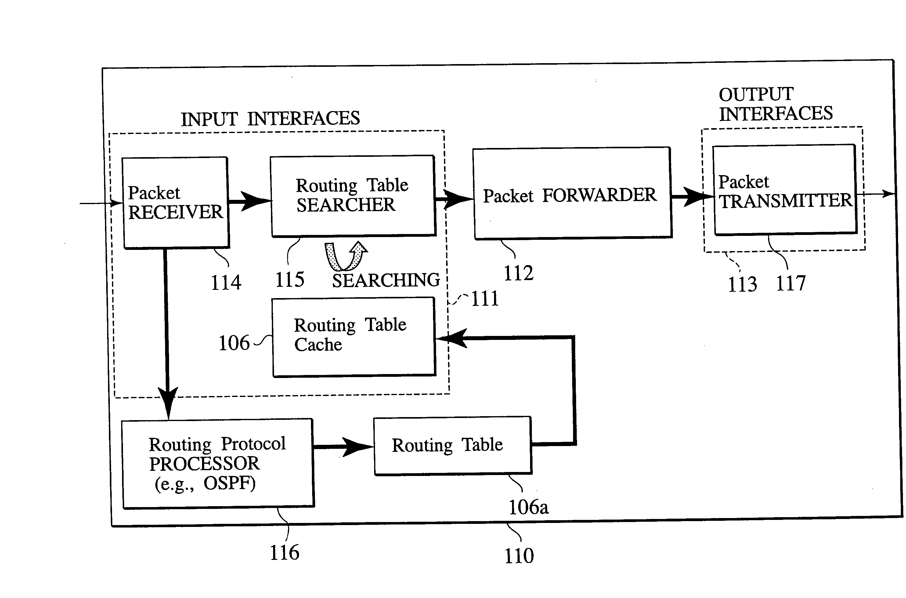
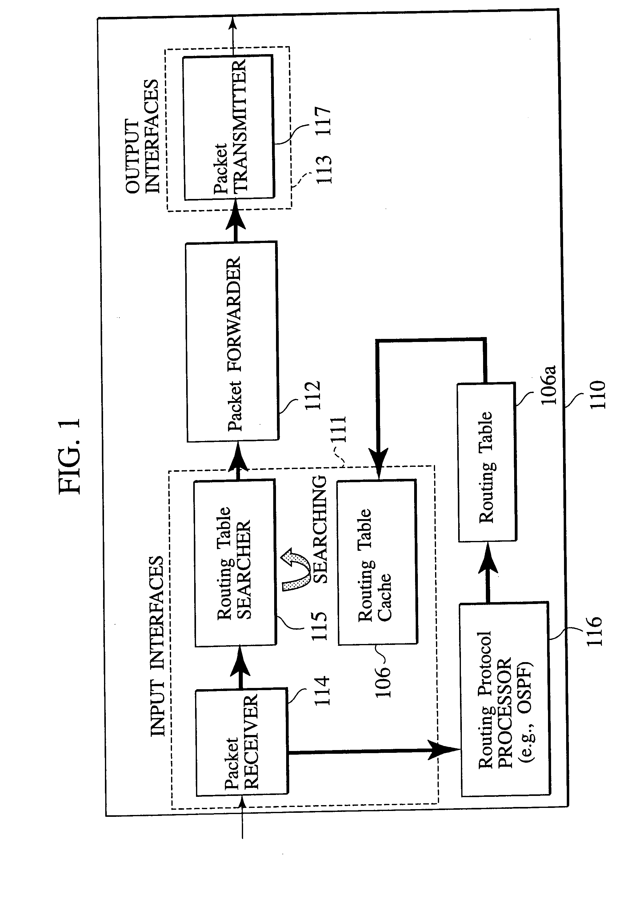
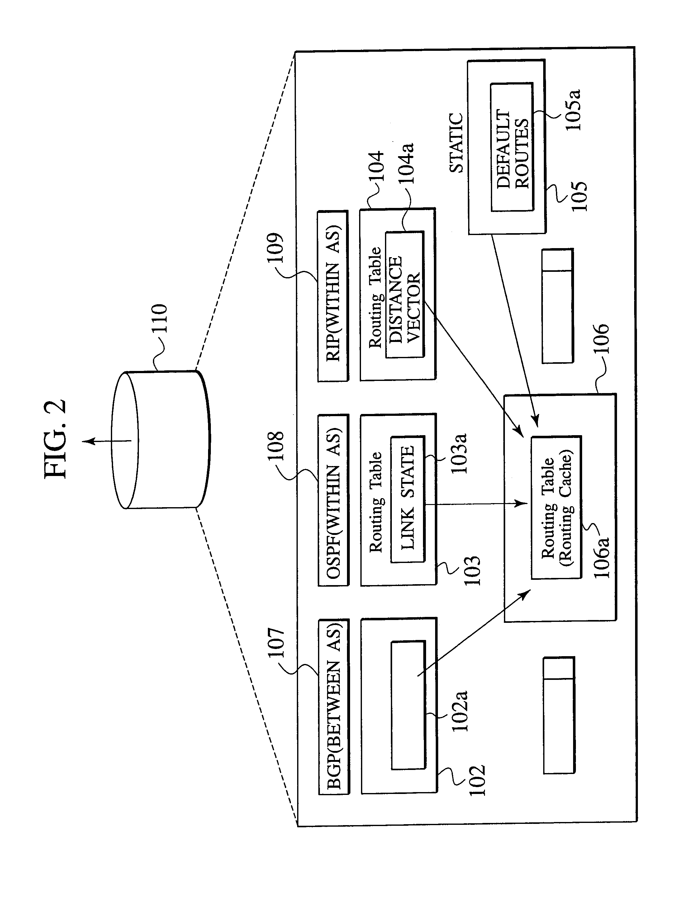

Image

  • Packet switching system, packet switching method, routing apparatus, structure of packet, and packet generating method
  • Packet switching system, packet switching method, routing apparatus, structure of packet, and packet generating method
  • Packet switching system, packet switching method, routing apparatus, structure of packet, and packet generating method

Examples


Embodiment Construction

[0036] An embodiment of a packet switching system according to the invention is described with reference to associated drawings. FIG. 3 schematically describes the overall configuration of the packet switching system according to the embodiment of the invention. Here, a routing of a packet from a client terminal 1 to a destination client terminal 2 via a route (1) through (7) on a packet switching network 100 will be described as a typical example.

[0037] As shown in FIG. 3, the packet switching network 100 is configured by interconnecting routing domains 10, 20, 30 and 40. Each routing domain is configured by routers. In FIG. 3, the routing domain 10 is configured by routers 11 through 13, the routing domain 20 is configured by routers 21 and 22, the routing domain 30 is configured by routers 31 through 34, and the routing domain 40 is configured by routers 41 through 43, respectively. The routing domains are interconnected via border routers 21, 31 and 41. A network management app...


PUM


Abstract

The packet switching system for transmitting and receiving a packet via a packet switching network 100, which comprises a plurality of routing tables (#0, #1, #2 . . . ), each of which has been generated by a unique routing policy, stored in the routing apparatuses deployed at the border, at the origin or at the end of the respective routing domains, an identifier (RTI) inserted in the packet to specify the routing tables, and an identifier changer to change a value of the identifier on the packet switching network 100. The routing apparatus selects one of the routing tables (#0, #1, #2 . . . ) according to the RTI in the received packet and transfers the packet to a destination that is specified by the selected routing table.

Description

CROSS REFERENCE TO RELATED APPLICATIONS [0001] This application is a continuation of application Ser. No. 10 / 331,661, filed Dec. 31, 2002, and claims the benefit of priority from the prior Japanese Patent Application No. P2002-003799, filed on Jan. 10, 2002. The entire contents of which are incorporated herein by reference.BACKGROUND OF THE INVENTION [0002] 1. Field of the Invention [0003] The present invention relates to a packet switching system, a packet switching method, a routing apparatus, a structure of packet, and packet generating method, which are configured to transfer packets via a packet switching network that is configured by interconnecting a plurality of routing apparatuses. [0004] 2. Description of the Related Art [0005] In the conventional packet switching network, such as the Internet for example, IP address is assigned to each host (terminal) so that a physical location of the host can be identified. Then a routing apparatus (hereinafter referred to as router) on...

Claims


Application Information

Patent Timeline
Patent Type & Authority Applications(United States)
IPC IPC(8): H04L12/56H04L45/122H04L45/243H04L45/52H04L45/60
CPCH04L45/00H04L45/122H04L45/60H04L45/24H04L45/52H04L45/123
Inventor OKAGAWA, TAKATOSHIHAYASHI, YASUHISAJO, MANHEEIHARA, TAKESHI
Owner NTT DOCOMO INC
Why Eureka
Try Eureka