Roller holder for motion guide device

Inactive Publication Date: 2008-01-24
HIWIN TECH
View PDF7 Cites 13 Cited by
  • Summary
  • Abstract
  • Description
  • Claims
  • Application Information

AI Technical Summary

Benefits of technology

[0011]The primary objective of the present invention is to provide a roller holder including a number of rollers or bearing members rotatably retained between spacers for engag

Problems solved by technology

However, the spacers are all in great surface contact with the rollers such that the contact area between the rollers and the spacers is greatly increased and such that the abrasion or scraping between the rollers and the spacers may be increased.
In addition, for coupling the rollers to the spacers, an annular groove is required to be machined or formed in each of the rollers for engaging with the protruded conne

Method used


Image

  • Roller holder for motion guide device
  • Roller holder for motion guide device
  • Roller holder for motion guide device

Examples


Embodiment Construction

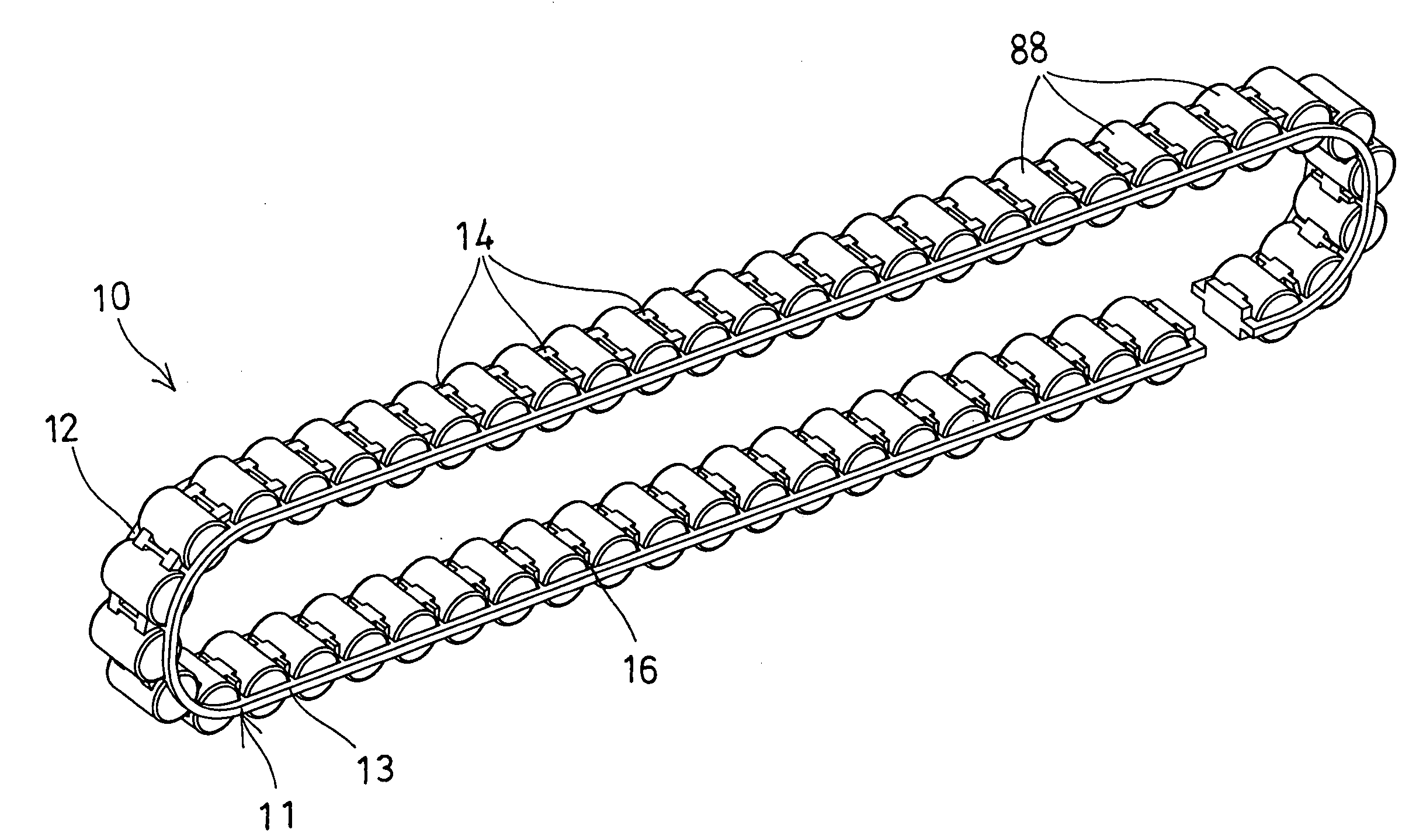
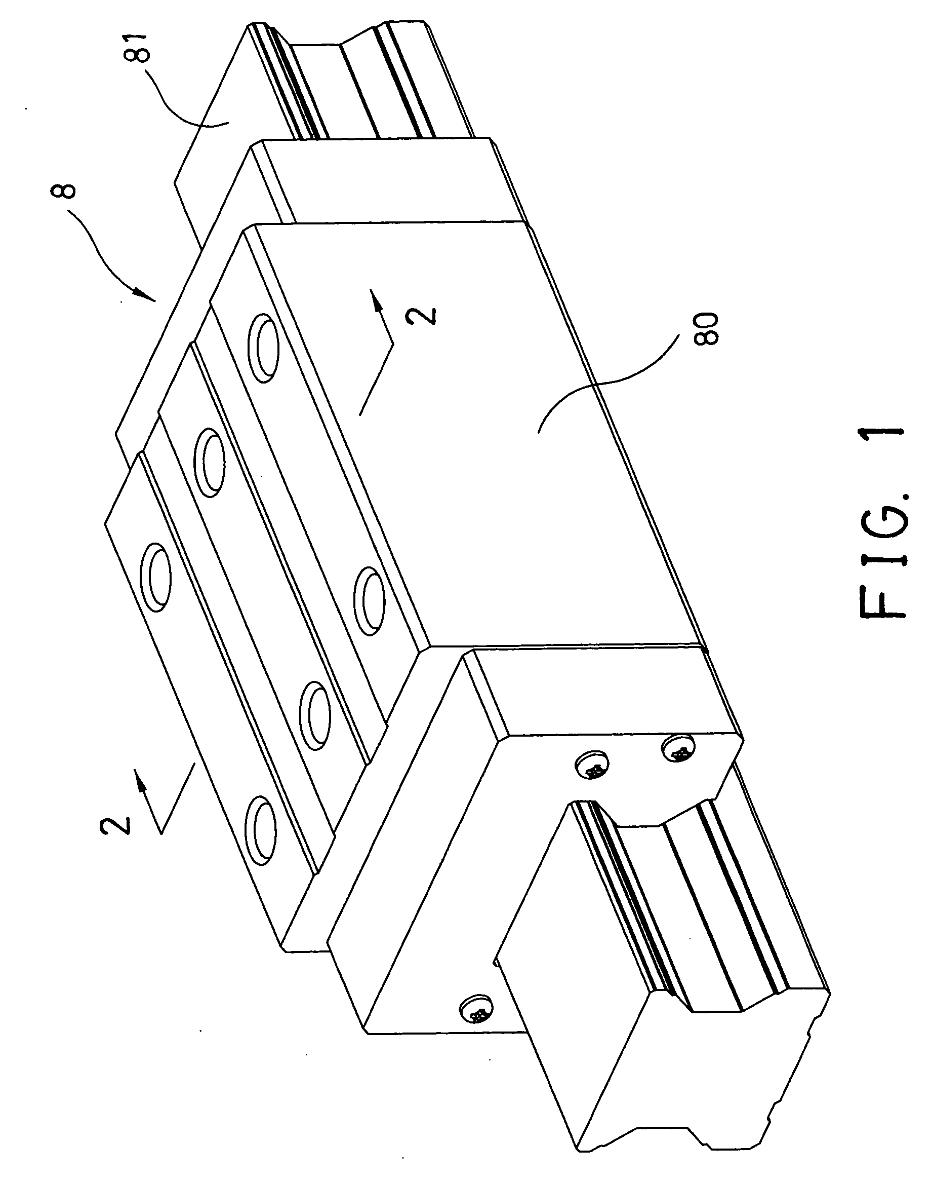
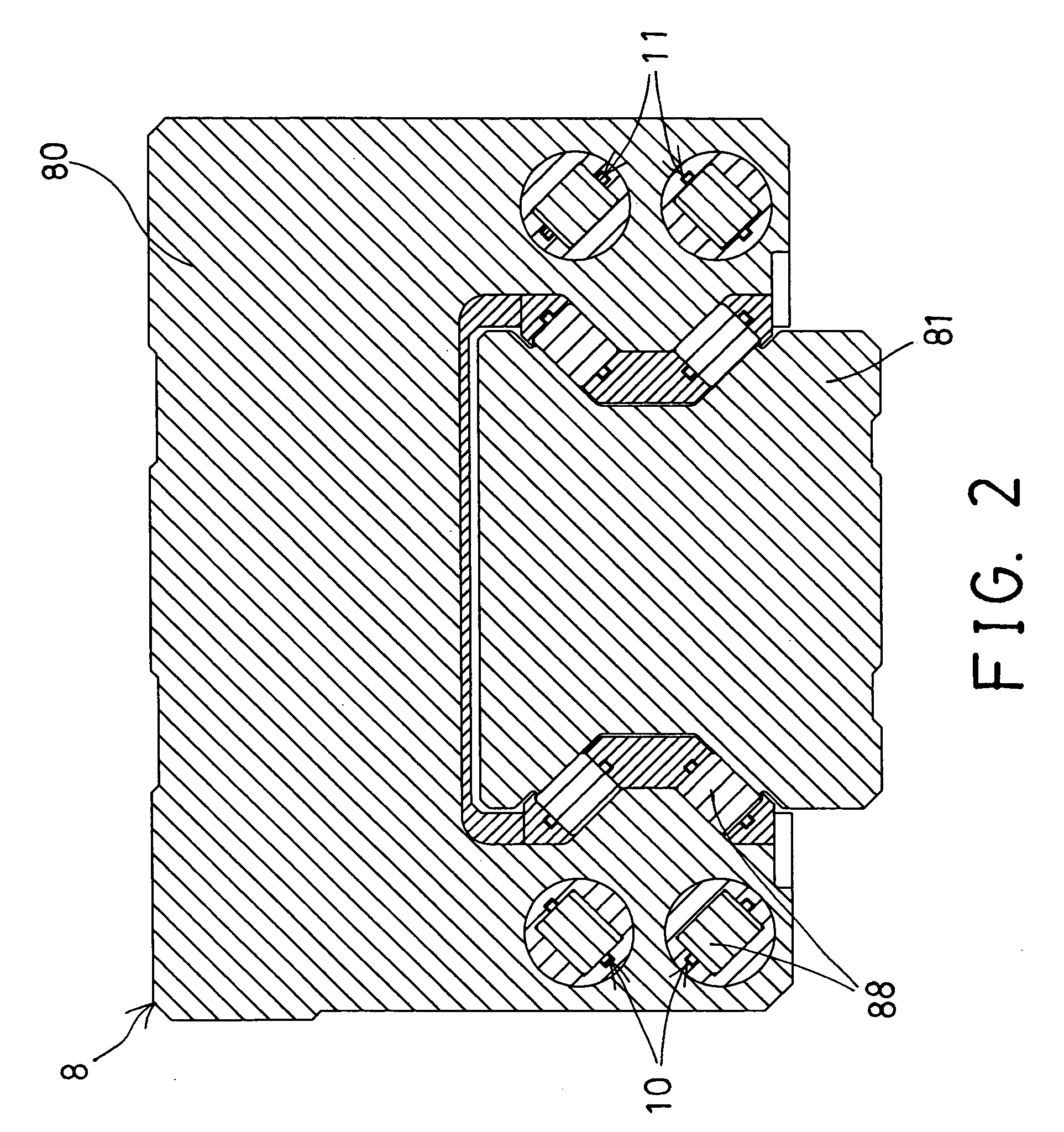
[0031]Referring to the drawings, and initially to FIGS. 1-4, a roller holder 10 in accordance with the present invention is provided for being engaged in a screw shaft device or linear motion guide device 8, such as engaged between a slider 80 and a track rail 81 of the linear motion guide device 8, and particularly engaged between the guiding channels of the slider 80 and the track rail 81, for facilitating the sliding movement between the slider 80 and the track rail 81 of the linear motion guide device 8. Similarly, the roller holder 10 in accordance with the present invention may be provided for facilitating the moving or sliding movement between any other two moving members that are moved relative to each other.

[0032]Referring next to FIGS. 3-11, the roller holder 10 in accordance with the present invention comprises an outer holding device 11 including one or more, such as two longitudinal and flexible cables or rods 12, 13 disposed or arranged parallel to each other, and arra...


PUM


Abstract

A roller holder includes an outer holding device having a number of spacers coupled to one or more rods and spaced from each other, the spacers each includes an upper portion located above the rods and a lower portion located below the rods, and each include two or more retainers disposed side by side, and a number of bearing members disposed and retained between the rods and the spacers, and the spacers each include two protrusions extended from each of the retainers for engaging with the bearing members and for decreasing a contact area between the bearing members and the spacers.

Description

BACKGROUND OF THE INVENTION[0001]1. Field of the Invention[0002]The present invention relates to a roller holder, and more particularly to a roller holder having a number of rollers or bearing members rotatably retained between spacers for engaging between two moving members and for decreasing the contact area between the rollers and the spacers and for facilitating the sliding movement between the two moving members.[0003]2. Description of the Prior Art[0004]Typical screw shafts comprise a screw member threaded into a nut member, or relatively, a nut member threaded onto a screw member, and a number of balls engaged in the threads of the nut member and the screw member for facilitating the rotational and / or sliding movement between the nut member and the screw member. Normally, the balls are simply disposed in the threads of the nut member and the screw member without any ball holders or retaining devices such that the balls may not be stably retained in place to each other.[0005]T...

Claims


Application Information

Patent Timeline
IPC IPC(8): F16C19/00
CPCF16C29/065F16C33/506F16C33/4676
Inventor CHEN, TSUNG JEN
Owner HIWIN TECH
Why Eureka
Try Eureka