Roller holder for motion guide device

Inactive Publication Date: 2007-10-18
HIWIN TECH
View PDF5 Cites 1 Cited by
  • Summary
  • Abstract
  • Description
  • Claims
  • Application Information

AI Technical Summary

Benefits of technology

[0009] The primary objective of the present invention is to provide a roller holder including a number of rollers alternately disposed and arranged in different directions for engaging between two moving members and for increasing the contact area between the two moving members and for facilitating the sliding movement between the two moving members.
[0010] In accordance with one aspect of the invention, there is provided a roller holder for engaging between two moving members, the roller holder comprising an outer holding device, a number of first rollers disposed in the outer holding device and partially extended out of the outer holding device, and a number of second rollers disposed in the outer holding device and partially extended out of the outer holding device and disposed alternately between the first rollers and arranged in different direction relative to the first rollers for engaging with different directions between the moving members and for facilitating the sliding movement between the two moving members. The first rollers and second rollers may be stably disposed and retained in the outer holding device in the stable or predetermined position relative to each other.

Problems solved by technology

However, the balls are in point-contact with the two moving members such that the abrasion or scraping between the-two moving members may be increased.

Method used


Image

  • Roller holder for motion guide device
  • Roller holder for motion guide device
  • Roller holder for motion guide device

Examples


Embodiment Construction

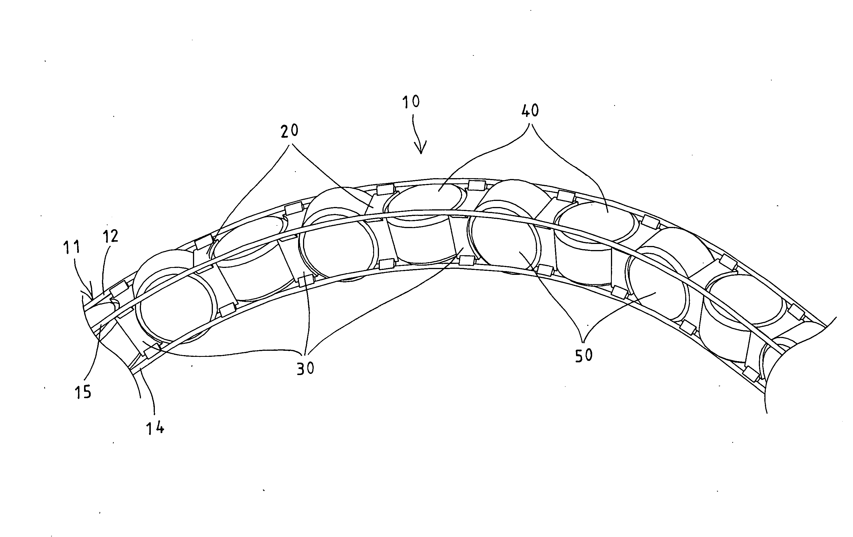
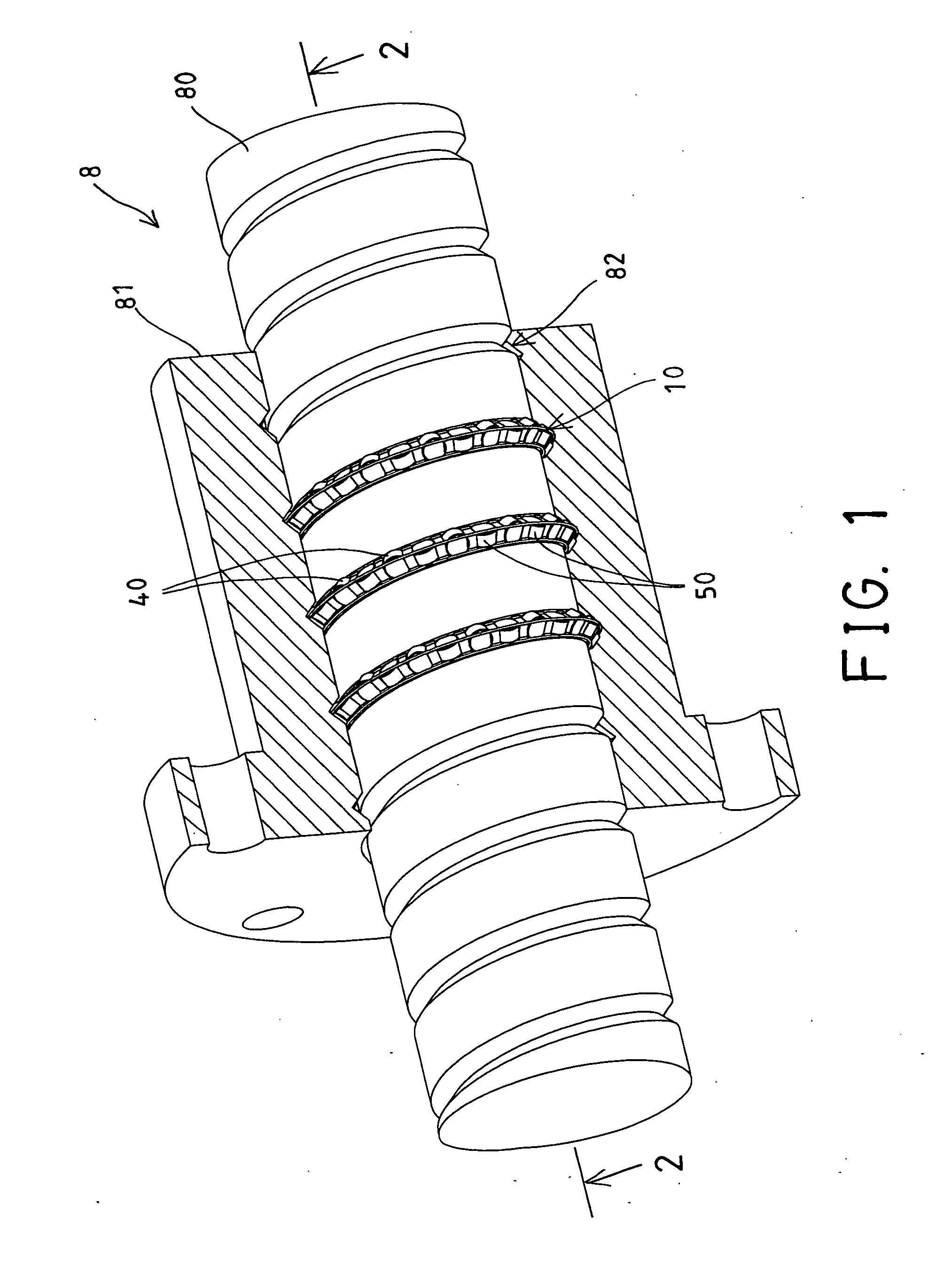
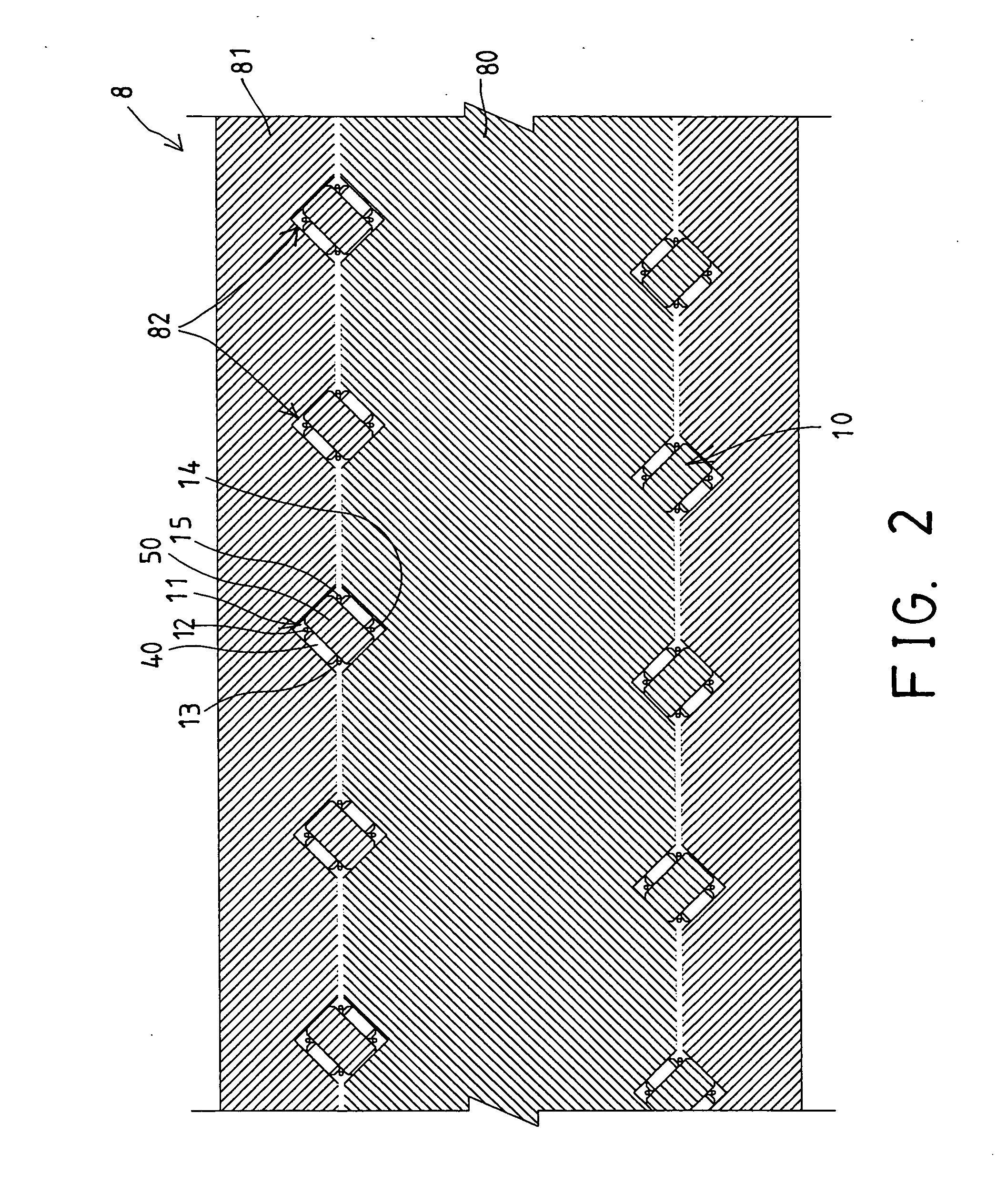
[0030] Referring to the drawings, and initially to FIGS. 1 and 2, a roller holder 10 in accordance with the present invention is provided for being engaged in a screw shaft device 8, such as engaged between a screw member 80 and a nut member 81 of the screw shaft device 8, and particularly engaged between the thread members 82 of the screw member 80 and the nut member 81, for facilitating the sliding movement between the two moving members or between the screw member 80 and the nut member 81.

[0031] As shown in FIG. 3, the roller holder 10 in accordance with the present invention may also be provided for being engaged in a linear motion guide device 83, such as engaged between a slider 84 and a track rail 85 of the linear motion guide device 83, and particularly engaged between the guiding channels of the slider 84 and the track rail 85, for facilitating the sliding movement between the slider 84 and the track rail 85 of the linear motion guide device 83. Similarly, the roller holde...


PUM


Abstract

A roller holder includes a number of rollers disposed in an outer holding device and partially extended out of the outer holding device and alternately disposed between the rollers and arranged in different direction relative to each other for engaging with different directions between two moving members and for facilitating the sliding movement between the two moving members. The outer holding device includes a number pairs of spacers disposed alternately relative to each other, and retained together with one or more flexible rods for retaining the rollers between the spacers. The spacers each include opposite curved recesses for rotatably receiving the rollers between the spacers.

Description

BACKGROUND OF THE INVENTION [0001] 1. Field of the Invention [0002] The present invention relates to a roller holder, and more particularly to a roller holder having rollers arranged in different directions for engaging between two moving members and for increasing the contact area between the two moving members and for facilitating the sliding movement between the two moving members. [0003] 2. Description of the Prior Art [0004] Typical screw shafts comprise a screw member threaded into a nut member, or relatively, a nut member threaded onto a screw member, and a number of balls engaged in the threads of the nut member and the screw member for facilitating the rotational and / or sliding movement between the nut member and the screw member. Normally, the balls are simply disposed in the threads of the nut member and the screw member without any ball holders or retaining devices such that the balls may not be stably retained in place to each other. [0005] Typical motion guide devices,...

Claims


Application Information

Patent Timeline
IPC IPC(8): F16C19/00
CPCF16C33/506F16C29/065
Inventor CHEN, YAN YU
Owner HIWIN TECH
Why Eureka
Try Eureka