Image sensing apparatus and control method therefor

a technology of image sensing apparatus and control method, which is applied in the direction of optical radiation measurement, instruments, television systems, etc., can solve the problems of affecting the detection effect of the main object, so as to prevent sudden sharp changes in exposure

Inactive Publication Date: 2008-01-31
CANON KK
View PDF5 Cites 36 Cited by
  • Summary
  • Abstract
  • Description
  • Claims
  • Application Information

AI Technical Summary

Benefits of technology

[0010]The present invention has been made in consideration of the above situation, and has as its object to prevent sudden sharp changes in exposure when an object that is a target temporarily cannot be detected, in an image sensing apparatus having a function that detects a particular object from image data and adjusts the exposure to the detected object.

Problems solved by technology

In an image sensing apparatus of this type, depending on the scene the determined exposure might cause improper luminance of the main object.
However, such a method burdens the user.
In these instances, the main object cannot be detected, and as a result, it becomes temporarily impossible to detect the main object despite the fact that the main object is in the same place within the frame.
If, for example, the subject is a child who finds it difficult to sit still, when carrying out detection of the main object with the method of JP-2002-251380-A there is a strong possibility that the main object temporarily fails to be detected.

Method used


Image

  • Image sensing apparatus and control method therefor
  • Image sensing apparatus and control method therefor
  • Image sensing apparatus and control method therefor

Examples


first embodiment

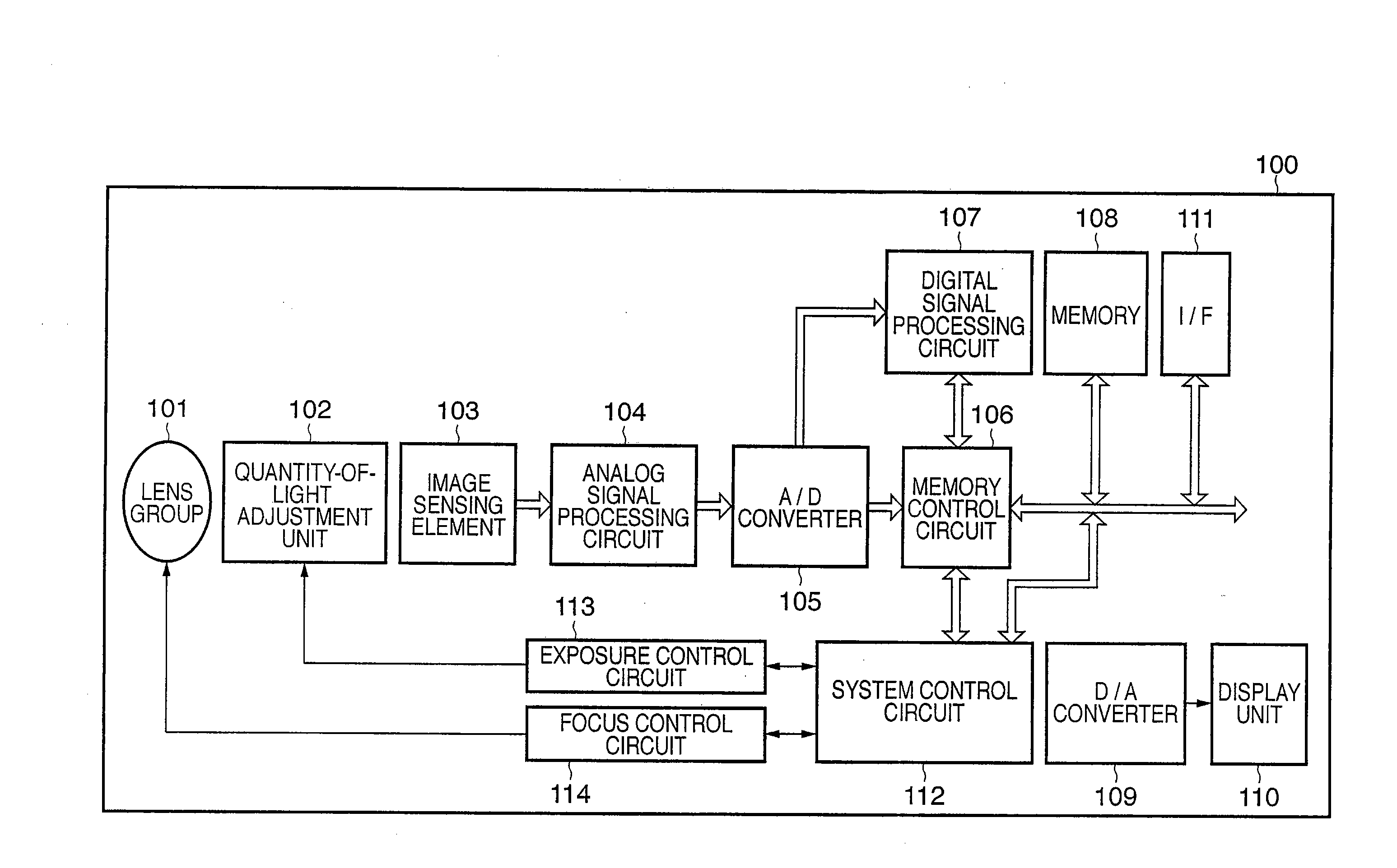
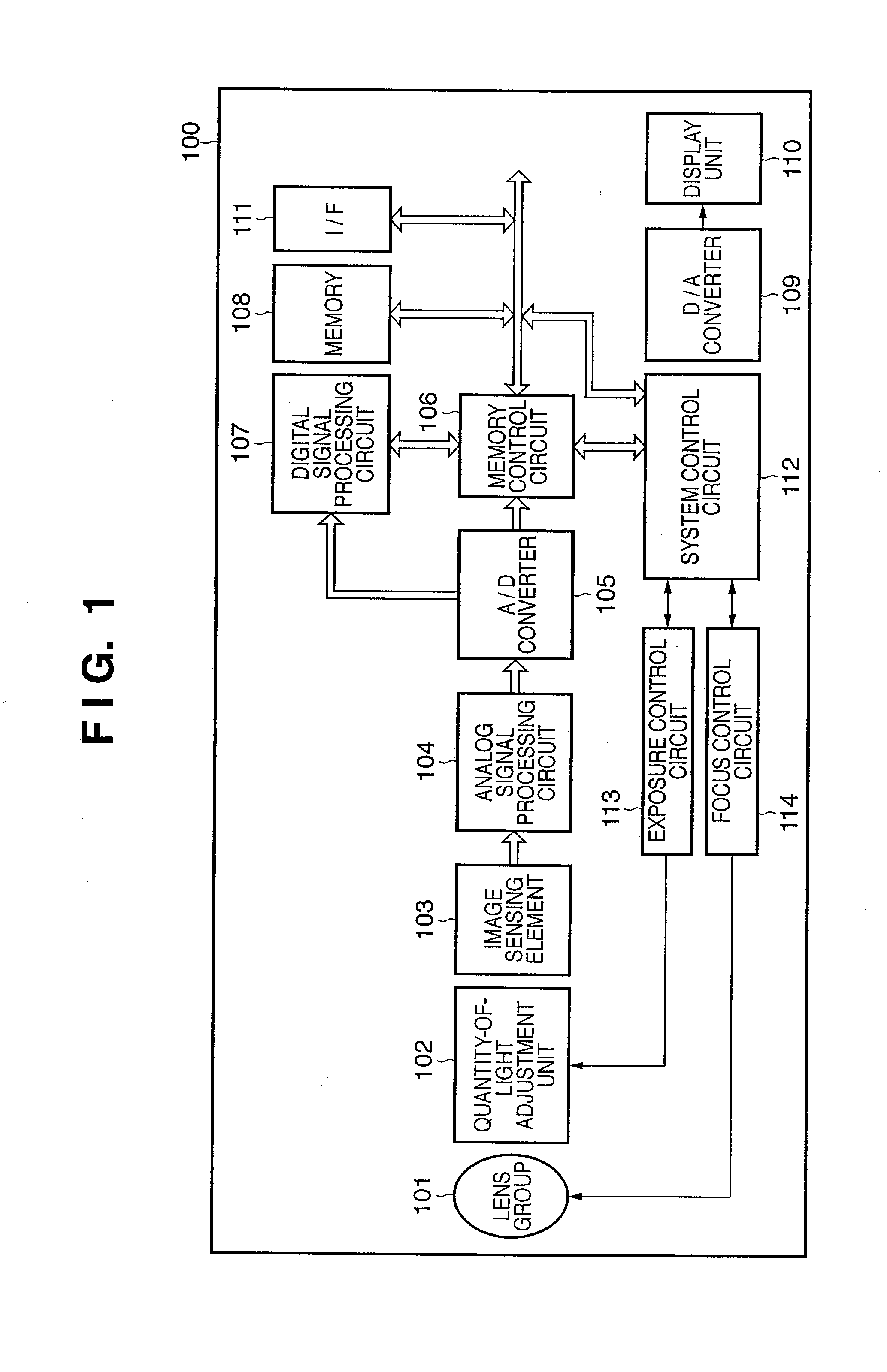
[0070]FIG. 1 is a block diagram showing the configuration of an image sensing apparatus 100 according to a first embodiment of the present invention.

[0071]In FIG. 1, the reference numeral 101 designates an image sensing lens group and 102 designates a quantity-of-light adjustment unit having an aperture device and a shutter device. The shutter device is a two-stage-type shutter. When a shutter button, not shown, is partially operated (for example, depressed halfway) and a shutter switch SW1 is switched ON, the start of such operations as AF (Auto Focus), AE (Auto Exposure), AWB (Auto White Balance) and EF (pre-flash) processing is instructed. Further, when the shutter button, not shown, is fully operated (for example, depressed fully) when the shutter switch SW1 is ON, a shutter switch SW2 is switched ON and the start of a series of processes consisting of an exposure process and a development process is instructed. Reference numeral 103 designates an image sensing element such as a...

second embodiment

[0140]Next, a description is given of a second embodiment of the present invention.

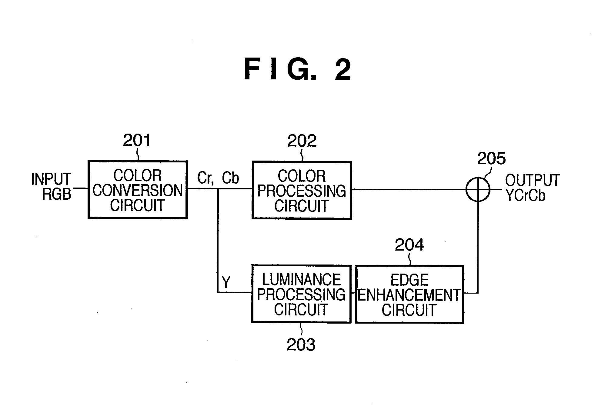
[0141]The second embodiment, as shown in FIG. 12, adds a BPF 1305 and a scene detection unit 1306 to the configuration of the digital signal processing circuit 107 described in the first embodiment with reference to FIG. 2. The remainder of the structure is the same as that described with reference to FIG. 1 and FIG. 2, and therefore identical reference numerals are attached thereto and a description thereof is omitted. In addition, the frame display process performed in step S113 shown in FIG. 3A is different from that of the first embodiment described with reference to FIG. 4. The remaining processes are identical to the processes described in the first embodiment, and therefore a description thereof is omitted and a description of the frame display process is given with reference to FIG. 13.

[0142]In FIG. 13, from step S401 to step S409 is the same as from step S401 to step S409 described with refer...

third embodiment

[0162]Next, a description is given of a third embodiment of the present invention.

[0163]The third embodiment differs from the first embodiment in that multiple faces are detected. In addition, and in consequence thereof, in step S202 shown in FIG. 5, the exposure control value acquisition method for the AE control carried out by the system control circuit 112 differs from that described in the first embodiment. The remaining processes are identical to the processes described in the first embodiment, and therefore a description thereof is omitted and the following describes the exposure control value acquisition method for AE control with reference to from FIG. 16 to FIG. 19, showing the state of display of the face detection frame. It should be noted that from FIG. 16 to FIG. 19 represents a continuously sensed scene. In addition, the predetermined time set in the timer is 0.6 seconds, the interval between continuously sensed scenes is 0.2 seconds, and a single face detection requir...


PUM


Abstract

An image sensing apparatus that carries out image sensing continuously and inputs a plurality of images, having a digital signal processing circuit that detects, at each input image, from image data thereof, an object that satisfies a preset condition, a first exposure value determination unit that calculates a first exposure value from the image data, a second exposure value determination unit that calculates a second exposure value based on the detected object, and a selection unit that selects either the first exposure value, the second exposure value, a currently set exposure value, or an exposure value calculated based on a luminance of an area referenced when calculating a currently set exposure value as an exposure value to be used for a next image sensing based on object detection results obtained by the digital signal processing circuit.

Description

BACKGROUND OF THE INVENTION[0001]1. Field of the Invention[0002]The present invention relates to an image sensing apparatus and a control method therefor, and more particularly, to an image sensing apparatus and a control method therefor that controls exposure according to a subject satisfying predetermined conditions.[0003]2. Description of the Related Art[0004]Conventionally, there is an image sensing apparatus equipped with an automatic exposure function that determines the exposure automatically with the entire frame being taken into account. In an image sensing apparatus of this type, depending on the scene the determined exposure might cause improper luminance of the main object. In order to obtain the proper luminance for the main object, there are apparatuses in which the user specifies the area in which the main object is present and the apparatus adjusts the exposure based on the specified area. However, such a method burdens the user.[0005]Meanwhile, there is an apparatus...

Claims


Application Information

Patent Timeline
Patent Type & Authority Applications(United States)
IPC IPC(8): H04N5/235H04N5/222G03B7/28G03B15/00G03B17/18H04N5/232
CPCH04N5/353H04N5/2351H04N23/71H04N25/53H04N23/72H04N23/611
Inventor TAKAHASHI, KENJI
Owner CANON KK
Why Eureka
Try Eureka