Object with rotational effect

a technology of rotating effect and object, which is applied in the direction of instruments, lighting and heating apparatus with built-in power, etc., can solve the problems of not providing power to continuously rotate and not providing a lighting device in the inner spherical shell

Inactive Publication Date: 2008-01-31
BENEXT INNO PROD DEV
View PDF5 Cites 27 Cited by
  • Summary
  • Abstract
  • Description
  • Claims
  • Application Information

AI Technical Summary

Benefits of technology

[0008]One of the embodiments of the present invention may be used as a globe. To prevent the illumination element from moving with the first enclosure shell, a second enclosure shell and a second liquid may be disposed between the first enclosure shell and the second enclosure shell, with the illumination element disposed in the second enclosure shell. This embodiment can achieve a special effect that can be found at the webpage www.mpegla.com / index1.cfm (i.e. a rotational globe).

Problems solved by technology

However, U.S. Pat. No. 5,893,789 does not provide power to continuously rotate the inner spherical shell, and also does not provide a lighting device in the inner spherical shell.

Method used


Image

  • Object with rotational effect
  • Object with rotational effect
  • Object with rotational effect

Examples


first embodiment

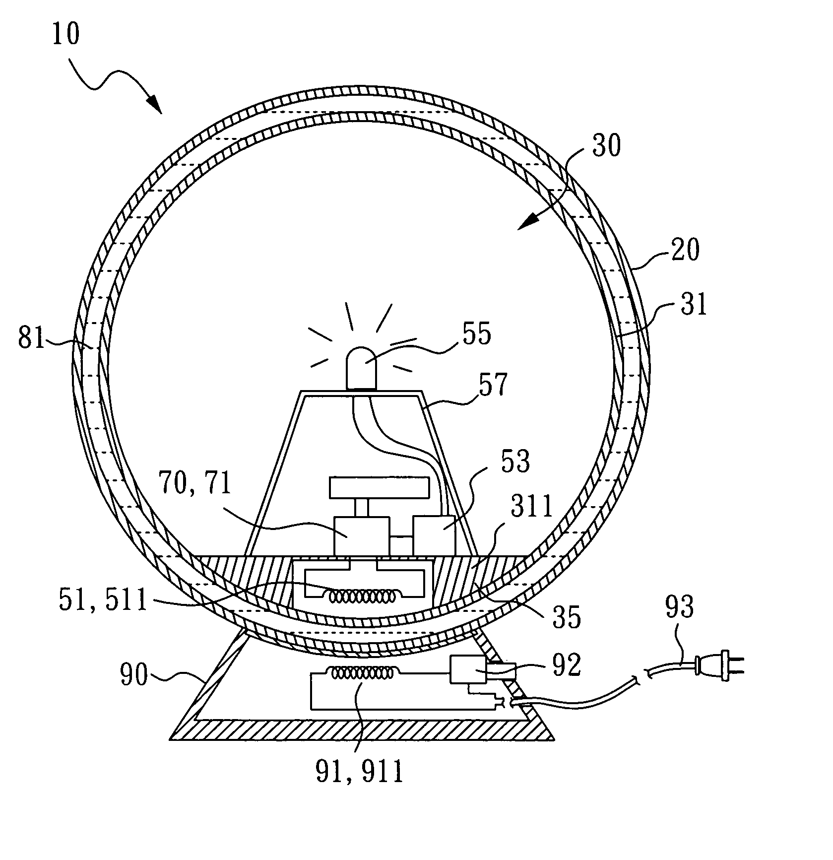
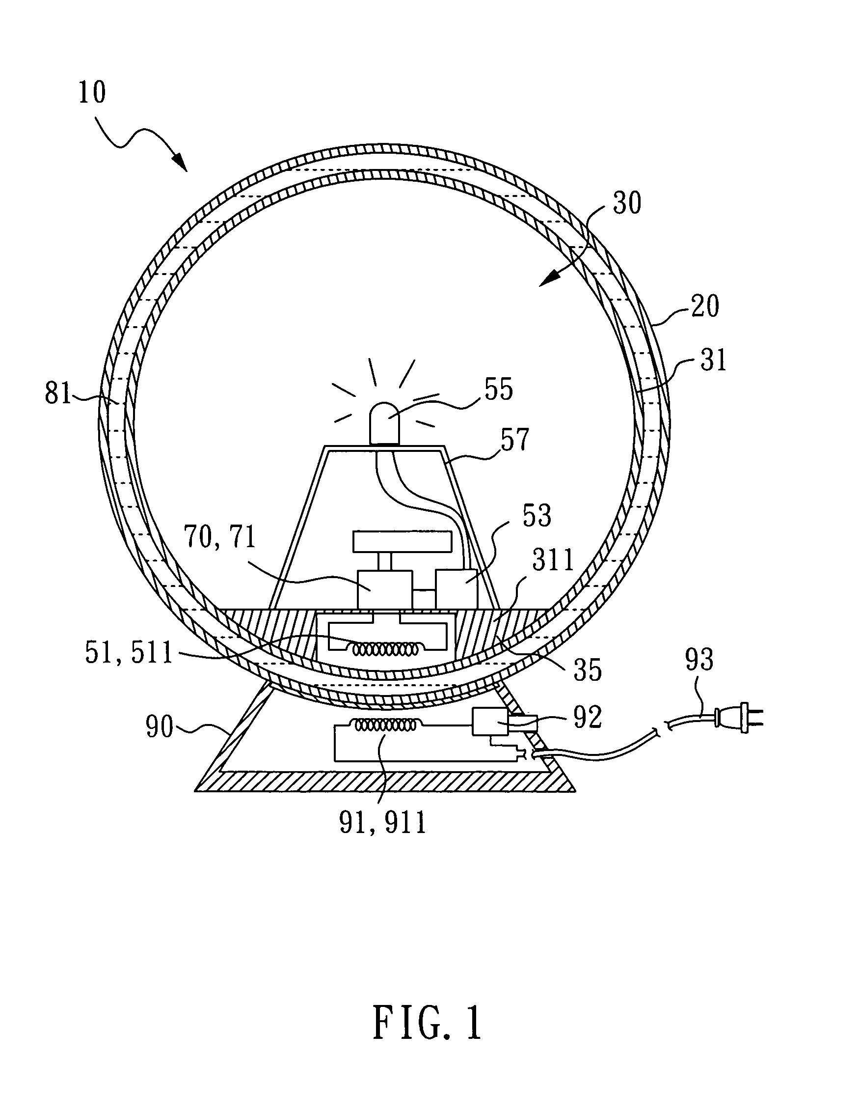
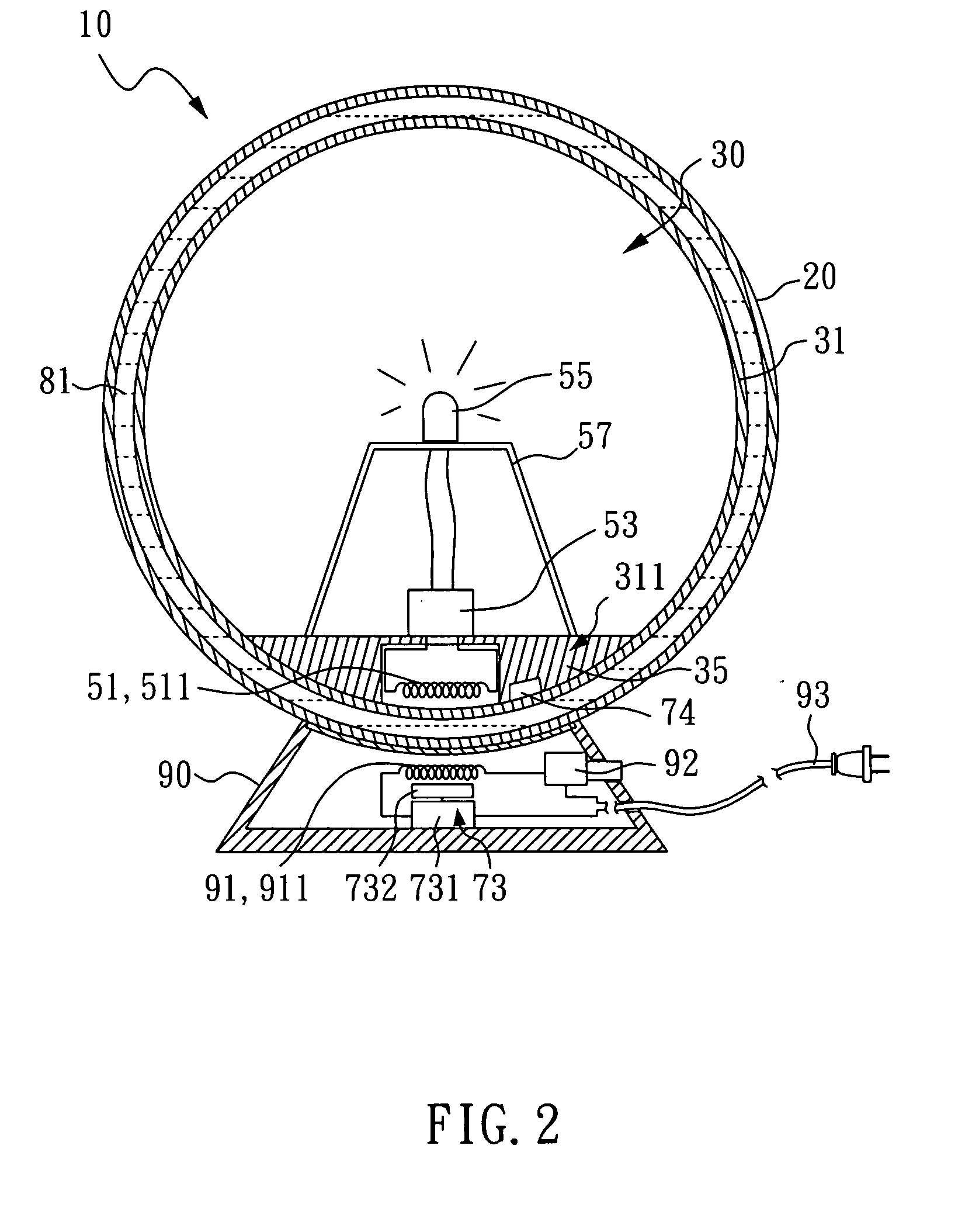
[0020]Please refer to FIG. 1 for a An object 10 having a rotational effect according to the present invention comprises three primary components: an outer enclosure shell 20, a base 90 and a first inner object 30. The first inner object 30 is disposed in the outer enclosure shell 20, and a first liquid 81 (such as water) is disposed in the space between the outer enclosure shell 20 and the first enclosure shell 31. The specific weight of the first inner object 30 is substantially equal to the specific weight of the first liquid 81 (the closer, the better) so that the first inner object 30 floats on or within the first liquid 81. If the first inner object 30 is too light, a heavier block 35 can be added onto the first inner object 30. Additionally, if the center of gravity of the first inner object 30 needs to be located lower within the object 30 to keep the bottom side 311 of the first inner object 30 pointed down, the heavier block 35 can be located on the bottom side 311, or clo...

fifth embodiment

[0038]With reference to FIG. 8, in the fifth embodiment, the outer enclosure shell 20 and the first inner object 30 in the object 10 each have a round, columnar shape.

sixth embodiment

[0039]With reference to FIG. 9, in the sixth embodiment, the outer enclosure shell 20 in the object 10 has a round columnar shape, and the first inner object 30 has the shape of a Christmas tree.


PUM


Abstract

An object with a rotational effect includes an outer enclosure shell, a base, a first inner object and a rotation device. The first inner object is located inside the outer enclosure shell. A liquid is filled between the first inner object and the outer enclosure shell. The base includes a power supply to transmit electrical power to the first inner object. The first inner object comprises a first enclosure shell, at least one illumination member and a power receiving member. The power receiving member receives electrical power from the power supply, and supplies electrical power to the illumination member. The rotation device rotates the first enclosure shell.

Description

BACKGROUND OF THE INVENTION[0001]1. Field of the Invention[0002]The present invention relates an object with a rotational effect, which can be used as an ornament or a globe.[0003]2. Description of the Related Art[0004]U.S. Pat. No. 5,893,789 (entitled “Sphere Toy”) discloses a sphere toy, which comprises an outer spherical shell, an inner spherical shell, and a liquid that is disposed between the outer spherical shell and the inner spherical shell. A user can use a rotation control device to control the rotation of the inner spherical shell. However, U.S. Pat. No. 5,893,789 does not provide power to continuously rotate the inner spherical shell, and also does not provide a lighting device in the inner spherical shell.SUMMARY OF THE INVENTION[0005]The present invention provides an object with a rotational effect that includes an outer enclosure shell, a base, a first inner object and a rotation device; the first inner object is located inside the outer enclosure shell. Additionally,...

Claims


Application Information

Patent Timeline
Patent Type & Authority Applications(United States)
IPC IPC(8): F21V33/00
CPCF21S9/02F21S10/002F21V3/02G09F19/02F21Y2101/02F21Y2115/10
Inventor LEE, KUO-VICENTLIAO, HO-HSIN
Owner BENEXT INNO PROD DEV
Why Eureka
Try Eureka