Communication relay apparatus, wireless terminal and computer program

Inactive Publication Date: 2008-02-14
MOTOROLA INC +2
View PDF5 Cites 7 Cited by
  • Summary
  • Abstract
  • Description
  • Claims
  • Application Information

AI Technical Summary

Benefits of technology

[0027] In addition, the evaluation of the delay time before and after switching the communication route, and the adjustment of the delay time difference make it possible to intend to solve problems

Problems solved by technology

However, in the above described related art described in “Seamless Handover in Mobile IP using SGM” and Japanese Patent Laid-Open No. 2004-228754, the communication is always performed via the gateway router or the HA, which makes a communication route redundant and causes problems of wasted communication resources, network congestion due to flow concentration, increased load on network devices and the like.
Furthermore, with respect to the handover between the heterogeneous systems, since delay times may be significantly different between the heterogeneous systems, the techniques described in “Seamless Handover in Mobile IP using SGM” and Japanese Patent Laid-Open No. 2004-228754, which secure real time reachability of the packets, are effective between the same wireless communication systems, however, between the heterogeneous systems having significantly different delay times, a seamless handover may not be realized due to the delay time difference.
Moreover, also in the technique described in Japane

Method used


Image

  • Communication relay apparatus, wireless terminal and computer program
  • Communication relay apparatus, wireless terminal and computer program
  • Communication relay apparatus, wireless terminal and computer program

Examples


Example

First Embodiment

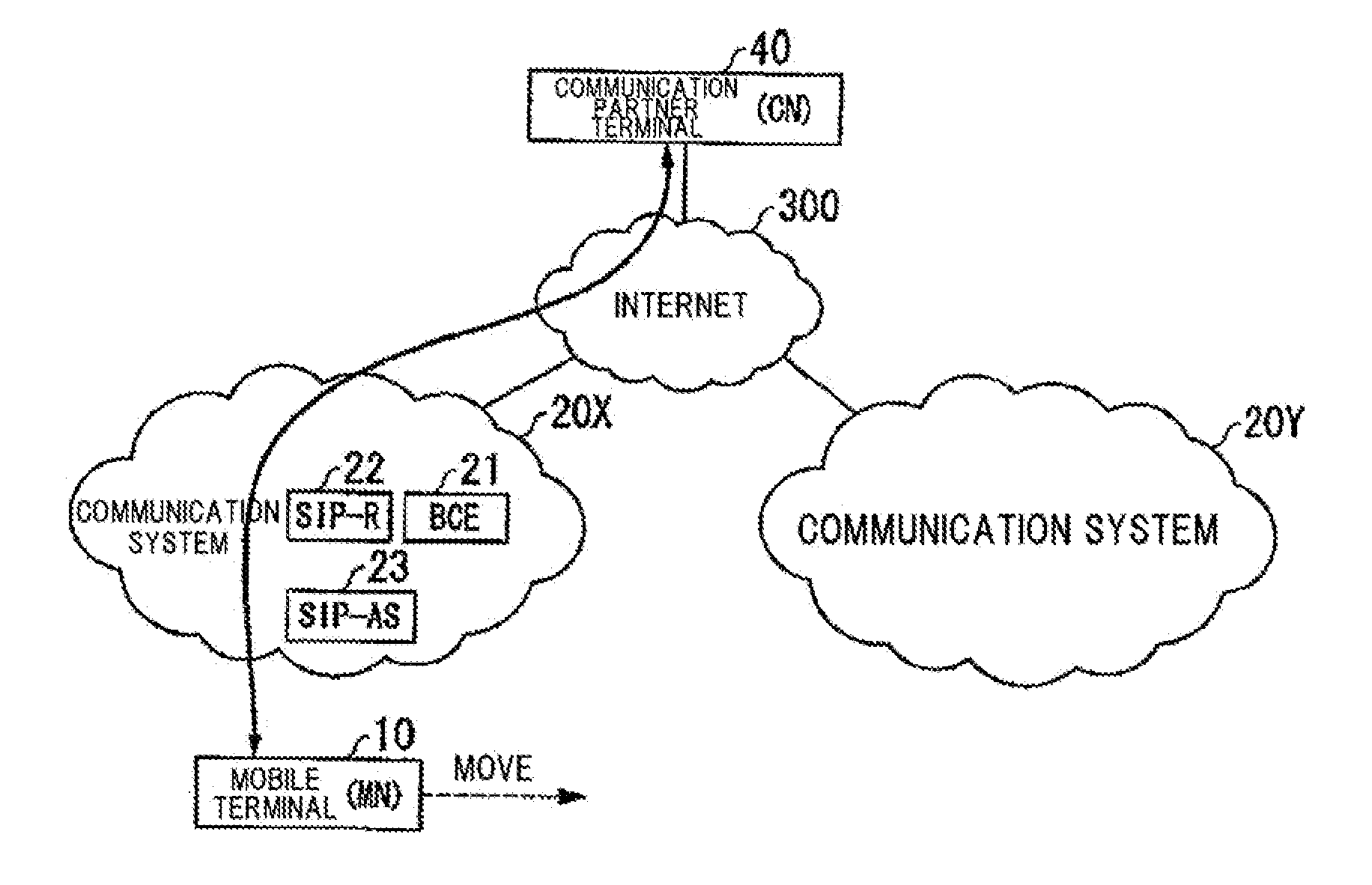
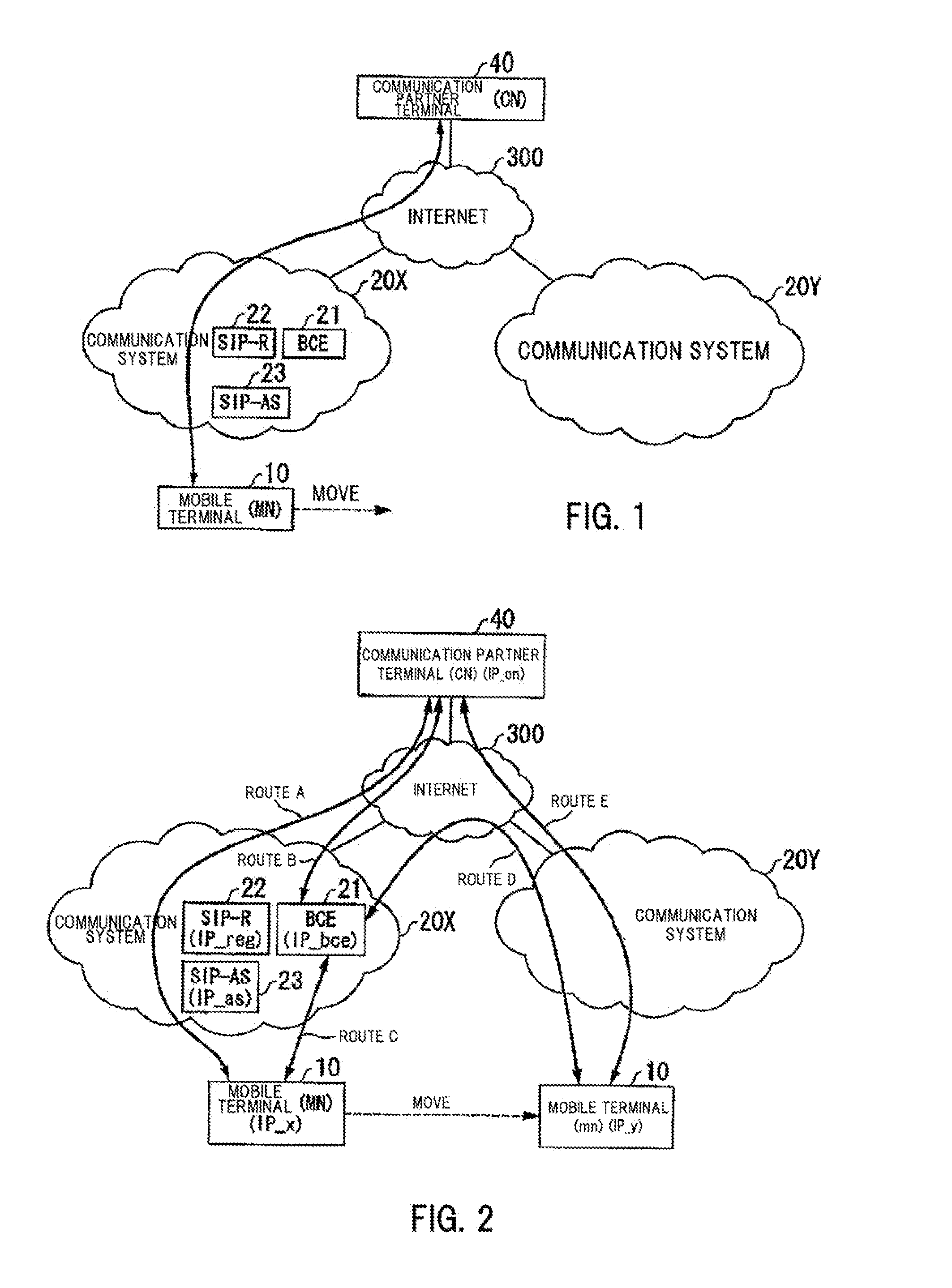
[0057]FIG. 1 is a block diagram showing a general configuration of a communication system according to a first embodiment of the present invention. In FIG. 1, a communication system 20X has a bicast entity (BCE) 21, a SIP registrar server (SIP-R) 22 and a SIP application server (SIP-AS) 23. The BCE 21, the SIP-R 22 and the SIP-AS 23 are configured to operate within the same node or operate in very close coordination. Moreover, the BCE 21 may be placed in a media gateway or in a home gateway at a user's home.

[0058] In FIG. 1, a mobile terminal (MN) 10 has communication interfaces for both of the communication system 20X and a communication system 20Y to connect to the communication systems 20X and 20Y, so that the MN 10 can communicate with a communication partner terminal (CN) 40 connected to the Internet 300, for example. Moreover, when a handover is performed between the communication systems 20X and 20Y, the MN 10 can connect to both of the communication systems...

Example

Second Embodiment

[0099]FIG. 15 is a block diagram showing a general configuration of a communication system according to a second embodiment of the present invention.

[0100] In the above described first embodiment, the bicast entity (BCE) is provided in only one of the two communication systems before and after the handover, while in the second embodiment, the BCE is provided in both of the communication systems before and after the handover.

[0101]FIG. 15 is the block diagram showing the general configuration of the communication system according to the second embodiment of the present invention. In FIG. 15, similarly to the configuration of FIG. 1, the communication system 20X has a BCE 21-1, the SIP-R 22 and the SIP-AS 23. On the other hand, the communication system 20Y has a BCE 21-2.

[0102] In FIG. 15, similarly to the system of FIG. 1, the mobile terminal (MN) 10 has the communication interfaces for both of the communication systems 20X and 20Y to connect to the communication...


PUM


Abstract

In order to continue a communication by performing a handover across or between different communication systems, improvement in redundancy of a communication route and a delay time difference before and after switching the communication system is intended. A bicast entity 21 includes, when a wireless terminal 10 makes a connection and continues a communication across different communication systems 20X and 20Y, bicast means for delivering a packet for each communication route via each of the communication systems 20X and 20Y before and after switching the communication system to which the above described wireless terminal 10 connects, and control means for completing a relay of the packet when the switching of the communication system to which the above described wireless terminal 10 connects is completed.

Description

BACKGROUND OF THE INVENTION [0001] 1. Field of the Invention [0002] The present invention relates to a communication relay apparatus, a wireless terminal and a computer program. [0003] 2. Description of the Related Art [0004] In recent years, with the development of wireless communication technology, it has been possible to use an application having real time property, such as a videophone application or a video streaming delivery application, on a mobile terminal. In order to realize smooth usage of such a real time application, a technique for securing the real time property of the communication when a handover is performed, in which the mobile terminal switches abase station to which the mobile terminal connects, has been considered. [0005] For example, in a technique described in “Seamless Handover in Mobile IP using SGM”, Institute of Electronics, Information and Communication Engineers, society convention in autumn, B-7-18, September 2001, under the condition in which the mobi...

Claims


Application Information

Patent Timeline
IPC IPC(8): H04Q7/20H04L12/701H04W36/00H04W36/02H04W36/14H04W36/38H04W40/34H04W76/02H04W80/04H04W80/10H04W92/02
CPCH04L65/1069H04W36/02
Inventor EGUCHI, HIDEHIKOFUKUHARA, TADAYUKIIZUMIKAWA, HARUKI
Owner MOTOROLA INC
Why Eureka
Try Eureka