Expanding trial stem for orthopaedic surgery

a trial stem and orthopaedic technology, applied in the field of expanding trial stems for orthopaedic surgery, can solve the problems of introducing further complications, affecting the clinical effect of patients, and not being able to meet the needs of joint kinematics assessment,

Active Publication Date: 2008-02-14
HOWMEDICA OSTEONICS CORP
View PDF17 Cites 30 Cited by
  • Summary
  • Abstract
  • Description
  • Claims
  • Application Information

AI Technical Summary

Problems solved by technology

Such features are not well-suited for use during the assessment of joint kinematics.
These devices, however tend to be bulky, complex and time consuming to set up and use.
They also require the use of external fixation devices and/or power tools that introduce further complications to the surgical procedure.
Because these devices exit through the incision to the outside of the body they are generally cumbersome making accurate range of motion assessment difficult.
While eliminating the problems ass...

Method used


Image

  • Expanding trial stem for orthopaedic surgery
  • Expanding trial stem for orthopaedic surgery
  • Expanding trial stem for orthopaedic surgery

Examples


Embodiment Construction

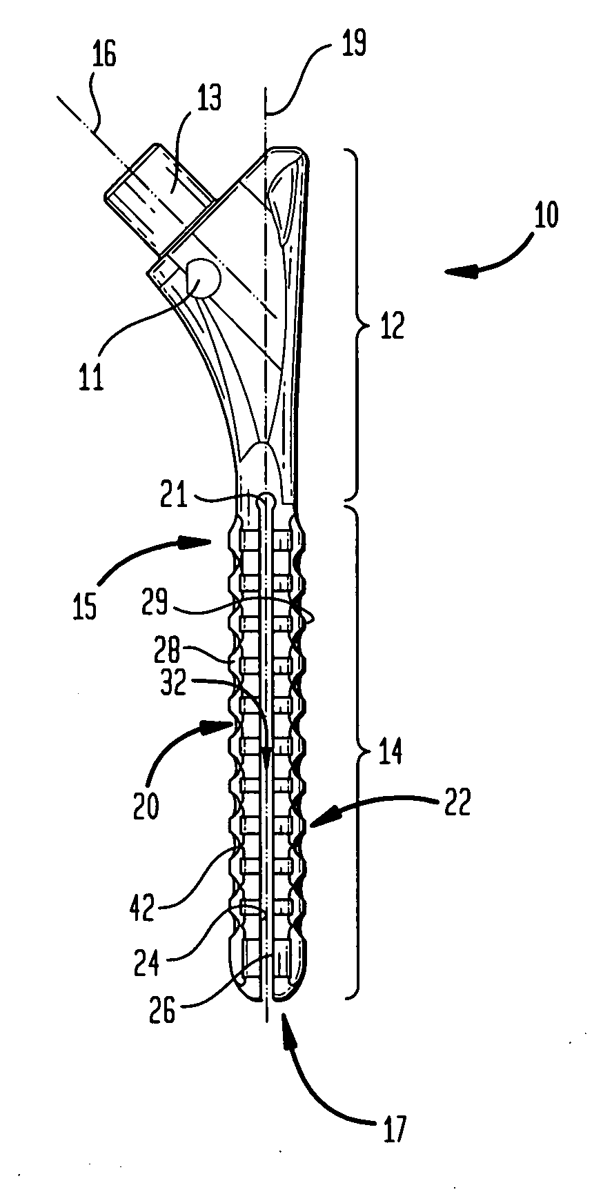
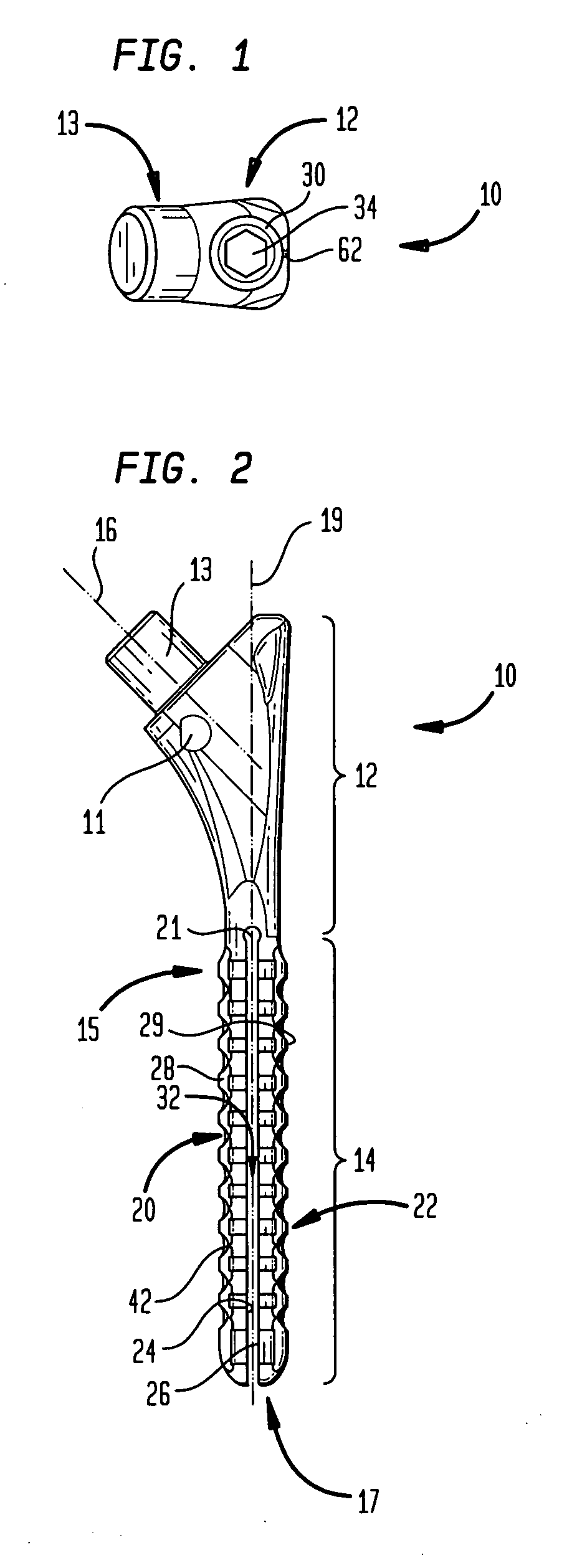
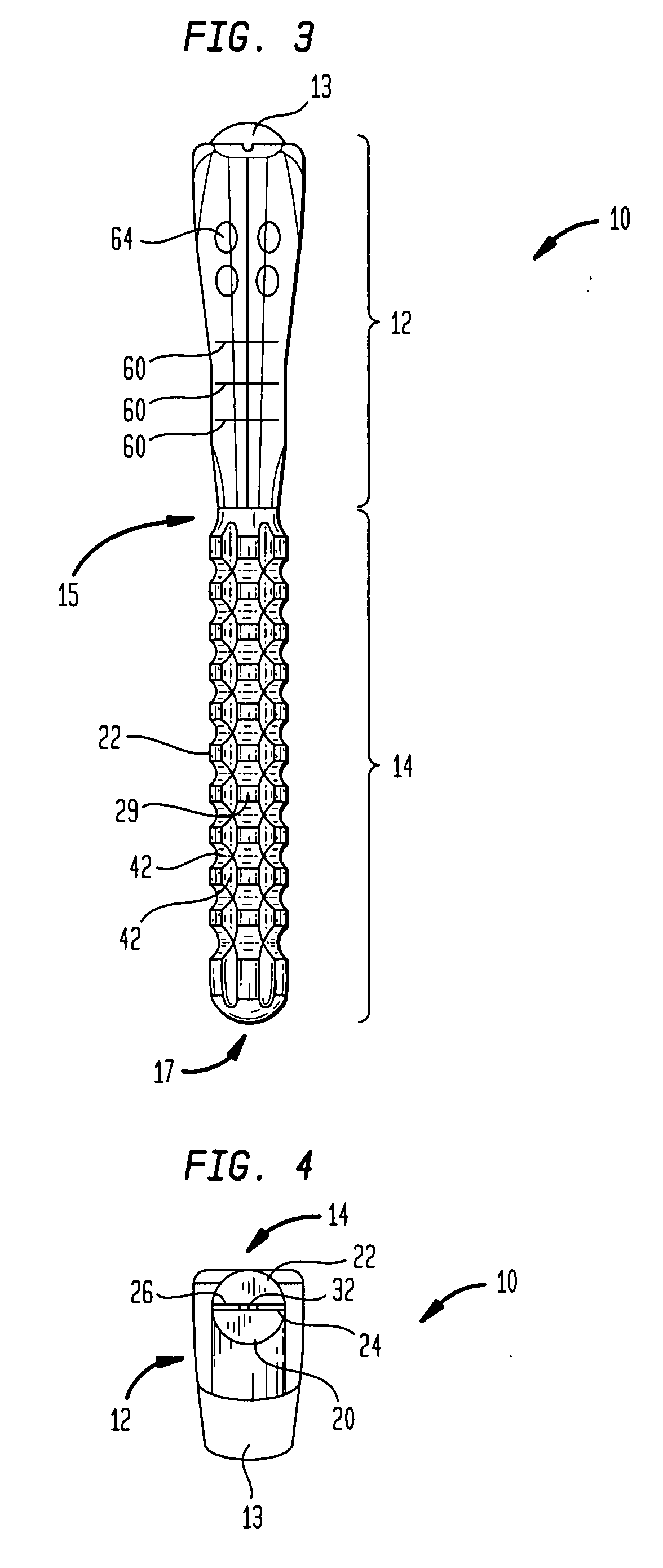
[0025]Referring to the drawings, wherein like reference numerals represent like elements, there is shown in FIGS. 1-4, in accordance with one embodiment of the present invention, a trial, designated generally by reference numeral 10. In describing preferred embodiments of trial 10, reference will be made to the directional nomenclature used in describing the human body. It is noted that this nomenclature is used only for convenience and that it is not intended to be limiting with respect to the scope or structure of the invention. When referring to specific directions, the device is understood to be described only with respect to its orientation and position during an exemplary application to the human body. As used herein when referring to bones or other parts of the body, the term “proximal” means close to the heart and the term “distal” means more distant from the heart. The term “inferior” means toward the feet and the term “superior” means toward the head. The term “anterior” m...


PUM


Abstract

A trial device and a method for using the device in surgery are disclosed. The device includes a body including a proximal portion and a distal portion. The proximal portion has a post or trunion projecting therefrom. The distal portion extends from the proximal portion and includes a first arm and a second arm, the first and second arms being moveable with respect to one another. The body further includes a cavity formed therein so as to extend through the proximal portion and into the distal portion. The device further includes a driver adapted for sliding engagement within the internal cavity of the body such that movement of the driver, preferably in a distal direction, causes movement of a portion of the first arm away from a portion of the second arm.

Description

BACKGROUND OF THE INVENTION[0001]A joint replacement procedure is sometimes necessary to repair a joint having a diseased or damaged articulating surface. Such a procedure involves removal of the diseased or damaged portions of the joint and replacing them with a prosthetic implant. This is often a desirable procedure for ball-and-socket type joints, particularly the shoulder and hip joints. A shoulder joint replacement procedure, for example, often involves removal of the humeral head and replacement thereof with an implant including a stem and a head. It is important that the implant be positioned correctly within the joint in order to ensure that appropriate joint kinematics, including range of motion, are preserved so as to replicate, as closely as possible, those of the original joint.[0002]The structure of prosthetic joint components has been developed to be suited for permanent implantation into the joint and includes features that may promote bony ingrowth, adhesion using ce...

Claims


Application Information

Patent Timeline
IPC IPC(8): A61F2/32
CPCA61F2002/3082A61F2002/30822A61F2002/30594A61F2/4684A61F2002/30579A61F2/36
Inventor SPLIETH, ROY PHILIPKROLL, SHAWN MICHAEL
Owner HOWMEDICA OSTEONICS CORP
Why Eureka
Try Eureka