Method of determination of a stuck point in drill pipes by measuring the magnetic permeability of pipes

a technology of magnetic permeability and determination method, which is applied in the field of oil drilling industry, to achieve the effect of reducing the cost of emergency maintenance works

Active Publication Date: 2008-02-21
SCHLUMBERGER TECH CORP
View PDF7 Cites 13 Cited by
  • Summary
  • Abstract
  • Description
  • Claims
  • Application Information

AI Technical Summary

Problems solved by technology

Drill pipes often get stuck in the hole during the drilling process carried out oil and gas drilling operations.
The main reasons of this undesirable situation are as follows: insufficient drilling mud circulation, which results in accumulation of sludge in the hole; insufficient drilling mud weight, which results in caving; excess drilling mud weight, which results in sticking; peculiarities of rock lithology (e.g. water-sensitive clays which swell in the presence of water); peculiarities of rock structure (e.g. some sedimentary rock may form long narrow lenses); tangential tectonic stresses, which results in caving; improper drilling mud composition, which results in inefficient or easily peelable mud cake; various faults of the drilling rig, derrick and underwater equipment, which results in long interruptions of pipe rotation, drilling mud movement or circulation; various faults of the pipe string; and human factors.
Pipe recovery is always unwanted but is frequently a necessary operation in the drilling.
If standard stuck-pipe releasing measures such as activation of drilling jars, increased drilling mud circulation, changes in the drilling mud weight, etc. prove to be inefficient, a remedial pipe recovery procedure is started.
Performing retrieval from too far above this free point results in loss of useful borehole space and in unnecessary loss of expensive tubulars.
Cutting the tubular string below the free point obviously results in no retrieval at all and severely complicates any possible remedial actions.
Emergency pulling of a string part is one of the most dangerous operations on the derrick and has the potential to cause injuries and even death of the personnel.
The overall accuracy of this method is limited by the resolution of the weight indicators on the hook and by the general design of the traveling block and draw-works drums of the drilling rig.
Also, if the well is deviated and / or the stuck point is close to surface, such measurements become difficult, imprecise, or impossible.
The necessity of continuous pipe movement endangers the personnel on the derrick and measurements are taken very slowly.
The sensitive part of this tool is manufactured in different diameters and, consequently, the slot between the pipe wall and the magnetic core is limited.
This method is not applicable to paramagnetic strings made of aluminum, stainless steel or Monel, for instance.
The applicability of the method is adversely affected by the fact that the position of the mark is associated with the logging odometer readings, and the accuracy of determination of the distance between the magnetic marks is therefore inevitably limited by depth measurement errors and is connected with a well-known mathematical problem of “small difference of big numbers”.
The disadvantage of the known method consists in the fact that the results of the stuck point determination greatly depend on the previous magnetization of the pipe and that it is impossible to use this method in paramagnetic strings.
The disadvantages of the known method include low sensitivity of the method and potential false indication of a free string in case of a high coercive force of the string metal, as well as in the necessity to take stationary measurements, which extends considerably the work period.
The disadvantages of the known method include its complexity resulting from the necessity to perform the operation of creation of discrete magnetic marks, as well as insufficient accuracy resulting from the discrete pattern of arrangement of the marks.
Thus, known downhole conventional systems have limitations.
The rig-up methods for such measurements are often complicated and dangerous to personnel involved.
The magnetic mark method precision is limited by the wireline depth control system resolution and so this method is often insufficiently precise.

Method used


Image

  • Method of determination of a stuck point in drill pipes by measuring the magnetic permeability of pipes
  • Method of determination of a stuck point in drill pipes by measuring the magnetic permeability of pipes
  • Method of determination of a stuck point in drill pipes by measuring the magnetic permeability of pipes

Examples


example

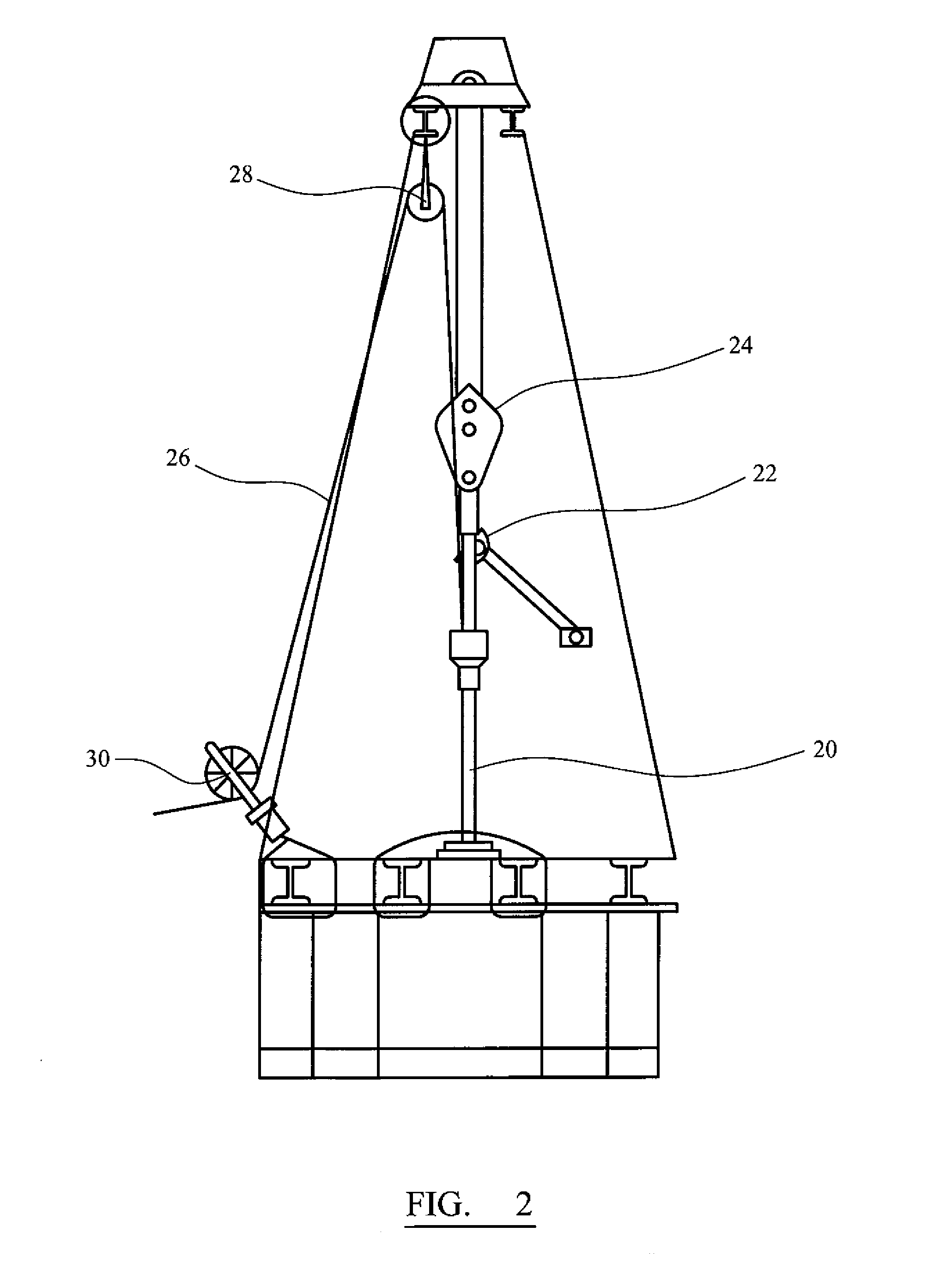
[0092] A specific example of implementation of the method of the present invention on a pilot unit, using a steel casing string 155 mm in diameter, is given below. The tool is run into the casing string in the same manner as is described above in relation to FIG. 2. The casing string is 1840 m long. After the first pass of the logging tool, the free point was determined at a depth of 1170 m from the surface. The pipe was loaded by being stretched, using a force equal to 0.95 of the ultimate mechanical strength. After the second pass of the logging tool, the free point was determined more precisely at a depth of 1158 m from the surface. Actually, the free point was at a depth of 1158.1 m.

[0093] The accuracy of the stuck point depth determination corresponds to the accuracy of the depth determination system of the logging tool used (i.e. ±0.15 m in the above example, assuming 0.15 m separation between logging stations).

[0094] Changes may be made while still remaining within the scop...


PUM


Abstract

The invention is a method of determining a free point in stuck drill pipes, comprising the steps of: a. measuring a first magnetic permeability (μ1) based on a time-induced decay of the electromagnetic field generated by application of an electric current pulse to the unextended pipe (l0); b. applying a force to the pipe to extend the pipe (l1); c. measuring a second magnetic permeability (μ2) of the extended pipe (l1) ; and d. comparing the first and second magnetic permeabilities (μ1 and μ2) along the drill string to determine the free point based on the change of magnetic permeability.

Description

TECHNICAL FIELD [0001] The invention relates to the oil drilling industry, and in particular, to surveying boreholes, and the determination of free or stuck parts of pipes in a borehole. BACKGROUND ART [0002] Drill pipes often get stuck in the hole during the drilling process carried out oil and gas drilling operations. The main reasons of this undesirable situation are as follows: [0003] insufficient drilling mud circulation, which results in accumulation of sludge in the hole; [0004] insufficient drilling mud weight, which results in caving; [0005] excess drilling mud weight, which results in sticking; [0006] peculiarities of rock lithology (e.g. water-sensitive clays which swell in the presence of water); [0007] peculiarities of rock structure (e.g. some sedimentary rock may form long narrow lenses); [0008] tangential tectonic stresses, which results in caving; improper drilling mud composition, which results in inefficient or easily peelable mud cake; [0009] various faults of th...

Claims


Application Information

Patent Timeline
Patent Type & Authority Applications(United States)
IPC IPC(8): G01V3/00E21B47/09E21B47/092
CPCE21B47/0905E21B47/092
Inventor ORBAN, JACQUESIAKIMOV, MIKHAIL
Owner SCHLUMBERGER TECH CORP
Why Eureka
Try Eureka