

Stabilized pad for vehicles
- Summary
- Abstract
- Description
- Claims
- Application Information
AI Technical Summary
Benefits of technology
Problems solved by technology
Method used
Image

Examples
second embodiment
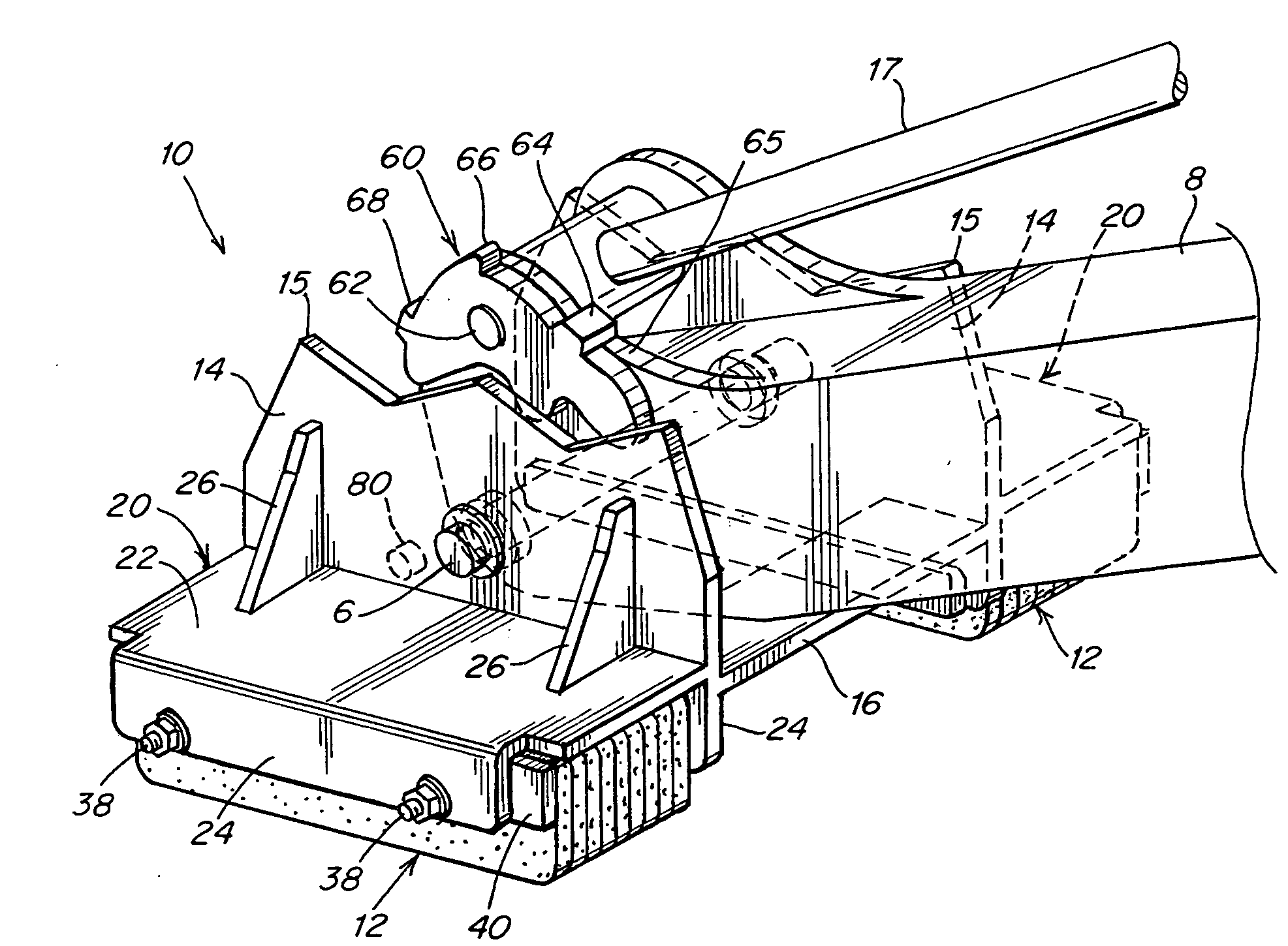
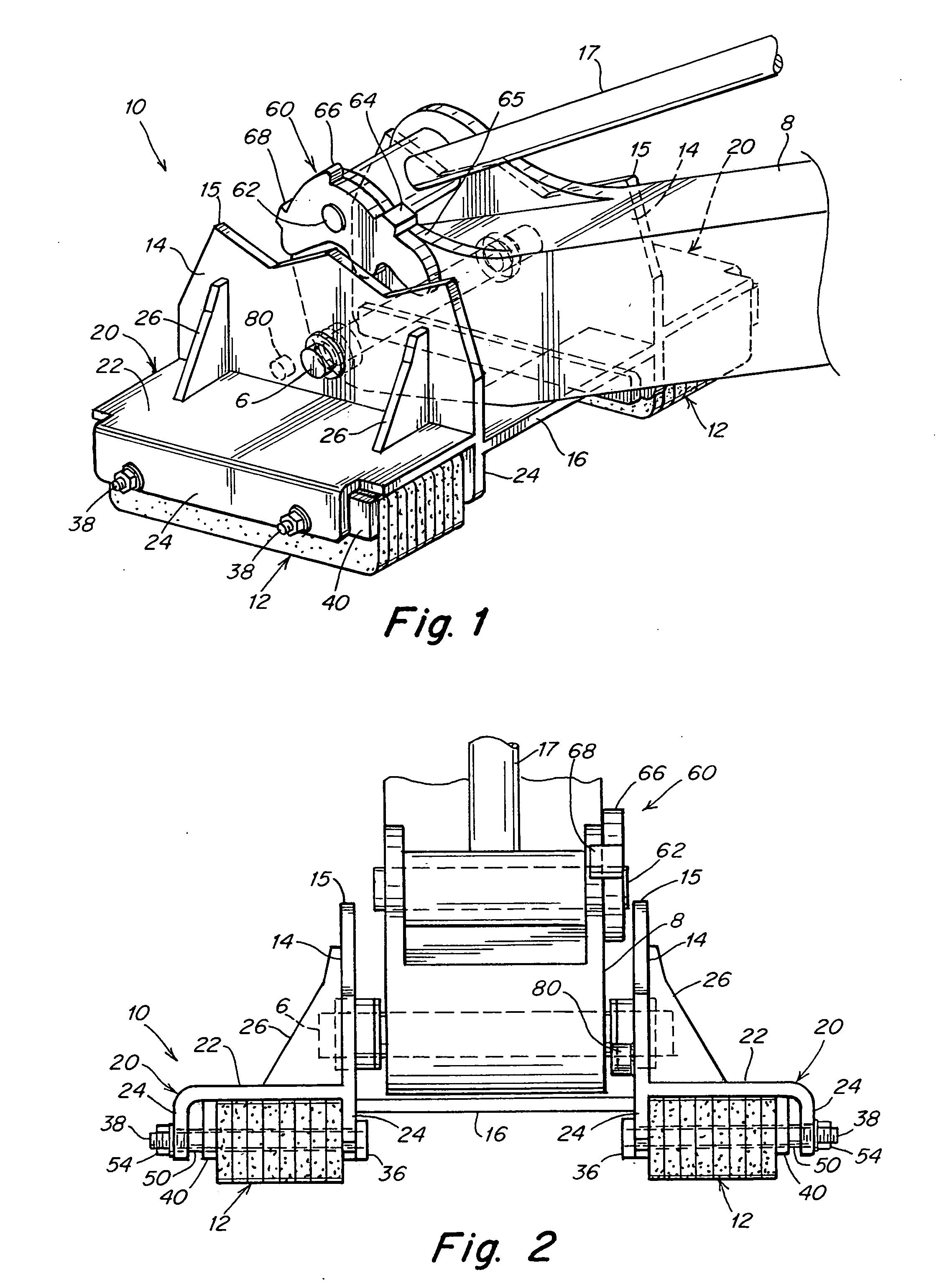
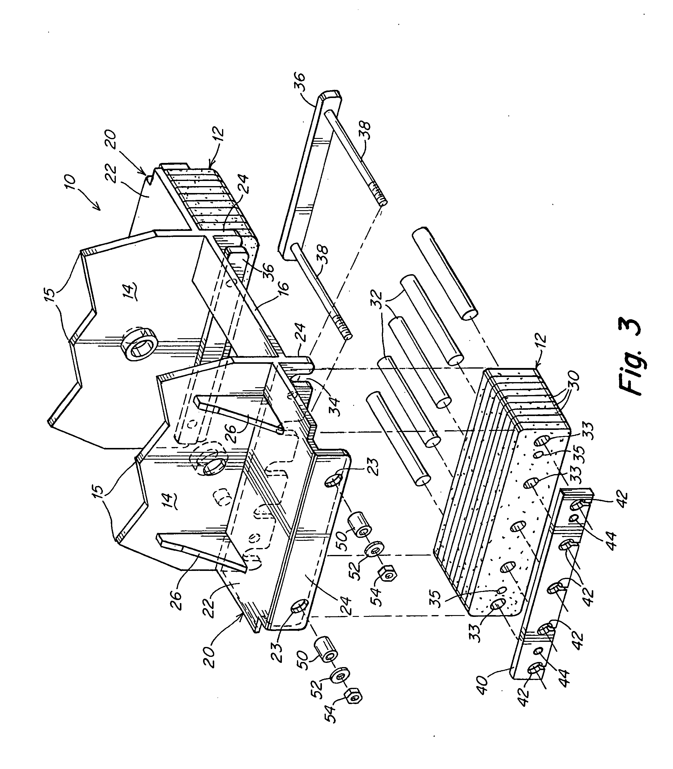
[0052]FIGS. 1 and 2 also show a first embodiment of the latch 60 of the present invention. FIGS. 16-18 show the latch arrangement of the invention. In both cases the latch member is preferably secured to the stabilizer arm, but alternatively could be secured to the pad itself. If the latch member were secured to the pad then the engagement lug is secured to the arm. In the illustrated embodiments the latch is pivotally supported from the arm and the engagement lug is supported from the pad, but is arranged in a position so that the lug traverses across the latch. In both embodiments the latch includes a capture means or element that engages with the engagement lug to prevent self-flipping of the pad. The latch and lug may be constructed of metal or a hard plastic material.
first embodiment
[0053]In the first embodiment the latch 60 is used to prevent self-flipping of the pad, particularly from the grouser side to the resilient pad side. The latch 60 is pivotally supported from the stabilizer arm 8 by means of the pivot pin 62. The latch can be positioned on either side of the arm 8. The latch member 60 is shown in its normal rest position in FIGS. 1 and 9. In that position the stop 64 rests upon and engages the arm surface 65, as noted in FIG. 1. FIG. 4 also illustrates the latch 60 with the stop 64 engaging the arm surface 65. The peripheral surface of the latch member 60 also includes a handle 66, a second stop 68, a capture recess 70 and nodes 72 and 74. The latch member 60 is also configured with a weighted end 76 that positions the latch as in the position of FIG. 4 with the stop 64 against the surface 65. With the weighted end 76 there is more weight on the right side of the pin 62 than the left side, as shown in FIG. 4. Alternatively, the latch member may be bi...
PUM
 Abstract
Description
Claims
Application Information