Tool-Mounting Attachment

a technology of mounting brackets and tools, which is applied in the direction of gear teeth manufacturing tools, grinding machines, gear teeth, etc., can solve the problems of inability to design the mounting opening with a plurality of curved sections, the inability to produce a great number of curved sections, and the inability to ensure the production of sufficient curved sections. to achieve the effect of precise seating of the mounting opening of the tool

Inactive Publication Date: 2008-03-06
C & E FEIN
View PDF6 Cites 30 Cited by
  • Summary
  • Abstract
  • Description
  • Claims
  • Application Information

AI Technical Summary

Benefits of technology

[0010] It is a first object of the present invention to improve a tool of the before-mentioned kind so that preci

Problems solved by technology

In the case of a relatively small diameter of the mounting opening it is, however, difficult to produce such a great number of curved sections, adapted to the corresponding driver elements of the drive shaft, and to adapt them to the driver elements of the drive shaft.
In particular when the tool is made from a relatively soft or ductile material, such as aluminum, sufficiently precise production of a the mounting opening with a great nu

Method used


Image

  • Tool-Mounting Attachment
  • Tool-Mounting Attachment

Examples


Embodiment Construction

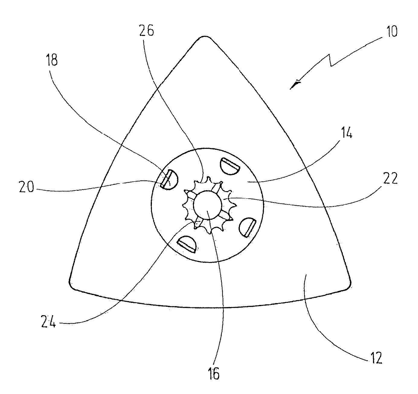
[0041]FIG. 1 shows a top view of a tool according to the invention in the form of a triangular grinding disk, indicated generally by reference numeral 10.

[0042] To enhance understanding, the drawing additionally shows at its center the axial end of a drive shaft 16 of an oscillating drive on which the mounting opening 22 of the tool 10 can be mounted in form-locking engagement.

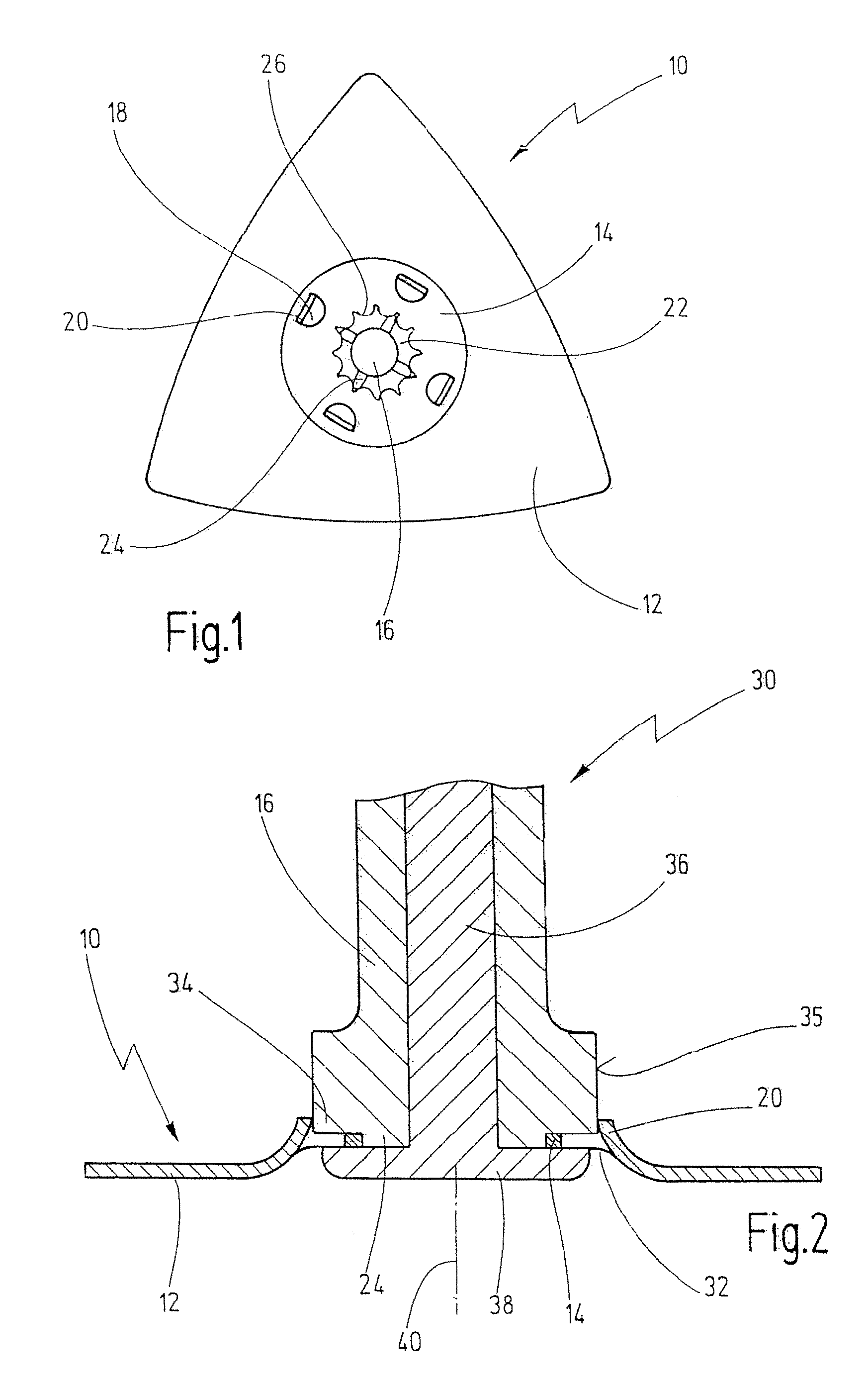
[0043] The tool 10 comprises a plane work plate 12 which preferably is provided with means for fastening an abrasive, such as a Velcro tape, which serves for fastening an abrasive in a detachable way. The work plate 12 is provided at its center with a mounting area 14 which is configured in such a way that a bent-off portion 32 projects over the remaining part of the work plate 12 (compare FIG. 2).

[0044] In the middle of the mounting area 14, there is provided a mounting opening 22 having a plurality of curved sections 26 formed symmetrically on the mounting opening 22, the arrangement comprising a total of...


PUM


Abstract

The invention discloses a tool having a work plate which has a mounting area with a mounting opening for mounting the plate on a drive shaft of a drive, preferably an oscillatory drive, the mounting opening being suitably configured for being seated on the drive shaft, wherein centering elements, projecting toward the drive shaft, are provided for centering the tool on the drive shaft.

Description

CROSS-REFERENCE TO RELATED APPLICATIONS [0001] This application claims Convention priority of German utility model application serial number 20 2006 013 890.0 filed on Sep. 1, 2006, the subject matter of which is fully incorporated by reference herewith. BACKGROUND OF THE INVENTION [0002] The present invention relates to a tool having a work plate which comprises a mounting area with a mounting opening for mounting the plate on a drive shaft of a drive, preferably an oscillating drive, the mounting opening being configured for being seated on the drive shaft. [0003] A tool of that kind is known from U.S. Pat. No. 6,945,862. [0004] The known tool is provided with a work plate comprising a mounting area with a mounting opening to be mounted on a drive shaft of an oscillating drive. The mounting opening is adapted for being seated in form-locking engagement on a plurality of flanks provided on the end of the drive shaft, and comprises curved sections adapted to the shape of the flanks....

Claims


Application Information

Patent Timeline
IPC IPC(8): B24B5/00
CPCB23B31/4073B24B45/00B24B23/04
Inventor SCHUMACHER, HERMANN
Owner C & E FEIN
Why Eureka
Try Eureka