Non-return valve for a pump

a technology of non-return valve and pump, which is applied in the direction of machines/engines, liquid fuel engines, positive displacement liquid engines, etc., can solve the problems of frequent breakage, and achieve the effect of long service life, easy and inexpensive manufacturing and assembly

Inactive Publication Date: 2008-10-14
SIEMENS AG
View PDF40 Cites 2 Cited by
  • Summary
  • Abstract
  • Description
  • Claims
  • Application Information

AI Technical Summary

Benefits of technology

[0017]The non-return valve according to the invention is used particularly for high-pressure fuel pumps in which very exacting requirements are placed on the individual components because

Problems solved by technology

Because of the bending radii between the stop region and the guide regions, breakages often occur, particularly

Method used


Image

  • Non-return valve for a pump
  • Non-return valve for a pump
  • Non-return valve for a pump

Examples


first embodiment

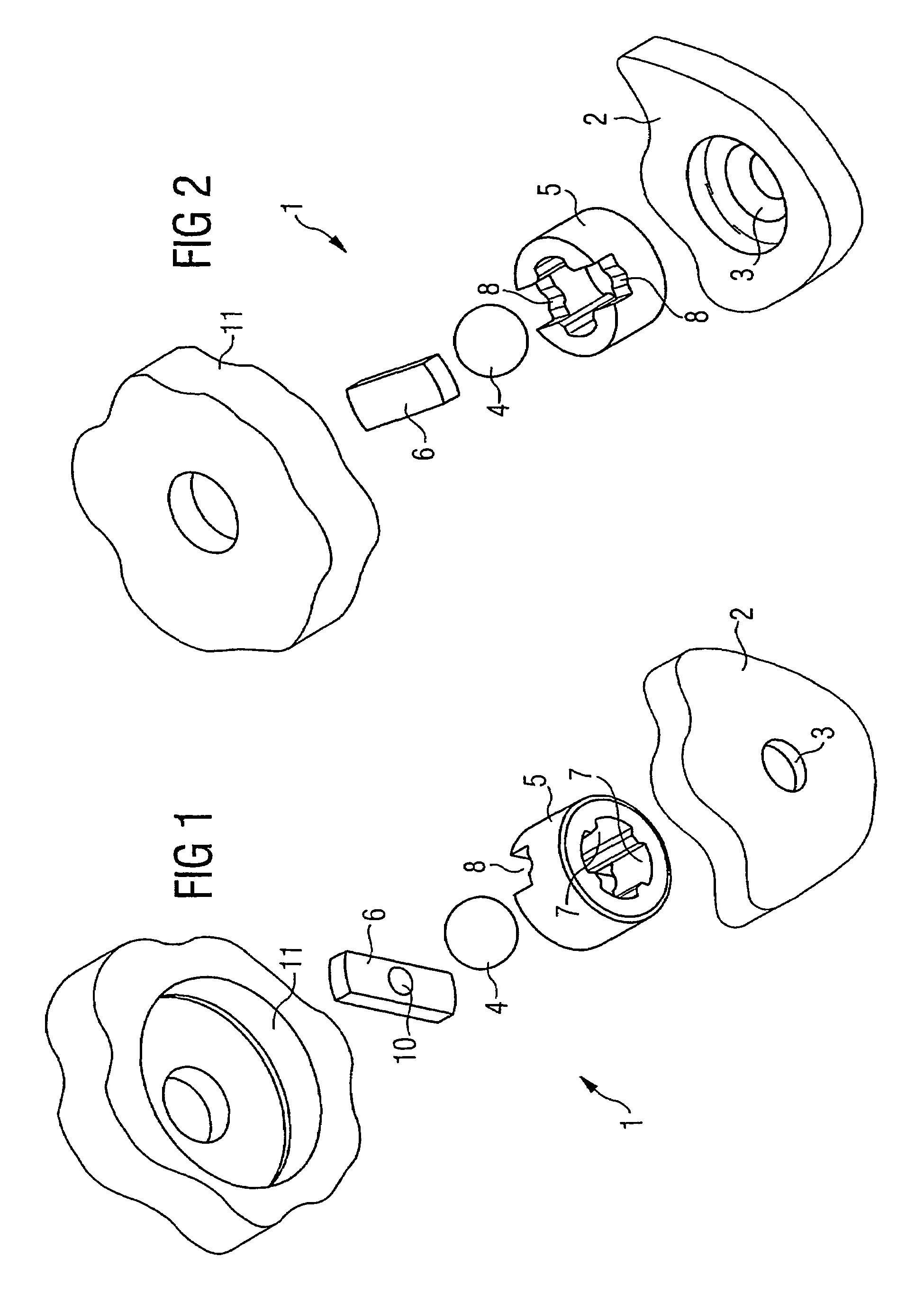
[0033]A non-return valve according to the present invention will now be described with reference to FIGS. 1 to 5b.

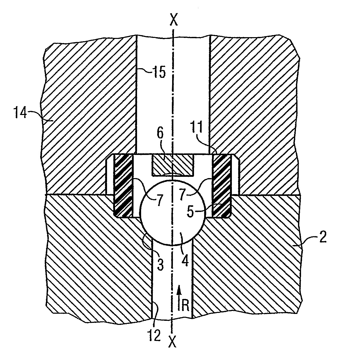
[0034]As shown in FIGS. 1 and 2, the inventive high-pressure non-return valve 1 according to the first embodiment comprises a receptacle 2 in which a valve seat 3 is implemented at the end of a line 12. As shown in FIG. 2, the valve seat 3 is implemented as a sealing cone. The valve 1 additionally comprises a two-part cage element consisting of a guide element 5 and a stop element 6. The stop element 6 is inserted in grooves 8 on the guide element 5.

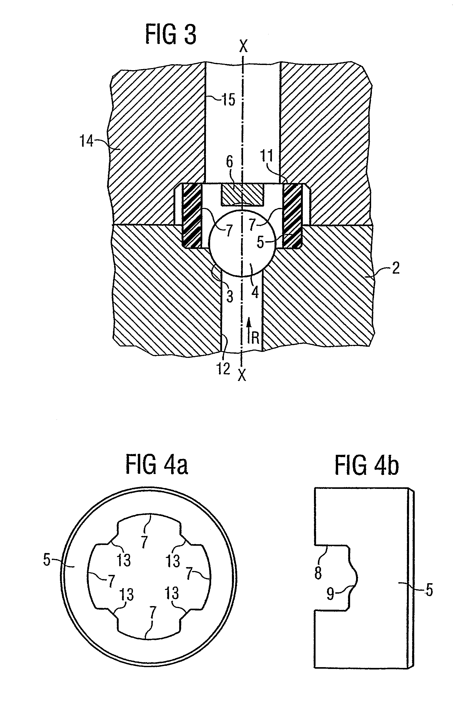
[0035]The guide element 5 is basically cylindrical in shape and has on its inside, as shown in FIG. 4a, four overflow passages 7 and four guide regions 13, the guide regions 13 being used to guide the closing body 4 implemented as a ball. The overflow regions 7 allow fluid to flow through the non-return valve in axial direction. As can be seen in particular from FIGS. 1 and 5a, a spherical indentation 10 is implemented in th...

fourth embodiment

[0043]FIGS. 8 and 9 depict a guide element and a stop element according to the present invention, identical parts being designated by the same reference characters.

[0044]As shown in FIG. 8, the guide element 5, in contrast to the first embodiment, has three grooves 8 into which a star-shaped stop element 6 shown in FIG. 9 can be press-fit, the three connecting regions of the stop element 6 each being disposed 120° apart, as shown in FIG. 9, and a press-fit being provided between the stop element 6 and the guide element 5.

fifth embodiment

[0045]FIGS. 10 and 11 show a guide element and a stop element according to the present invention, identical parts being designated by the same reference characters.

[0046]In the fifth embodiment, in contrast to the fourth embodiment, four grooves 8 are provided so that four connecting regions are also implemented on the stop element 6. The stop element 6 therefore has an essentially cruciform shape.

[0047]The present invention therefore relates to a non-return valve for a pump, in particular a fuel pump, having a receptacle 2, in which a valve seat 3 is implemented, a closing body 4 and a cage element. The closing body 4 is disposed in the cage element, said cage element being implemented in two parts. The cage element comprises a guide element 5 and a stop element 6, thereby providing functional separation of the cage element regions having different functions.


PUM


Abstract

The invention relates to a non-return valve for a pump, in particular a fuel pump, with a housing (2) in which a valve seat (3) is embodied, a closing body (4) and a cage element. The closing body (4) is arranged within the cage element, whereby the cage body is embodied in two pieces. The cage element comprises a guide element (5) and a stop element (6), such that a functional separation of the regions of the cage element with various functions is possible.

Description

CROSS REFERENCE TO RELATED APPLICATION[0001]This application is a continuation of copending International Application No. PCT / DE02 / 03166 filed Aug. 29, 2002 which designates the United States, and claims priority to German application no. 101 42 609.7 filed Aug. 31, 2001.TECHNICAL FIELD OF THE INVENTION[0002]The present invention relates to a non-return valve for a pump and in particular a high-pressure non-return valve for a fuel pump of a common rail injection system.DESCRIPTION OF THE RELATED ART[0003]Non-return valves for pumps are known in different embodiments. An example of a known non-return valve is illustrated in FIG. 12. As shown in FIG. 12, the non-return valve comprises a receptacle 2 having a valve seat 3 and also incorporates a closing body 4 and a cage element 16. The closing body 4 is disposed inside the claw-shaped cage element 16 and can move in axial direction in the non-return valve. The closing body 4 can assume two positions, namely a first position in which i...

Claims


Application Information

Patent Timeline
IPC IPC(8): F16K15/04F04B1/04F04B53/10
CPCF04B1/0452F04B53/1007F16K15/04Y10T137/7911Y10T137/791Y10T137/7914
Inventor HOHMANN, MARC
Owner SIEMENS AG
Why Eureka
Try Eureka