

Fiber bundle termination with reduced fiber-to-fiber pitch
- Summary
- Abstract
- Description
- Claims
- Application Information
AI Technical Summary
Benefits of technology
Problems solved by technology
Method used
Image

Examples
Embodiment Construction
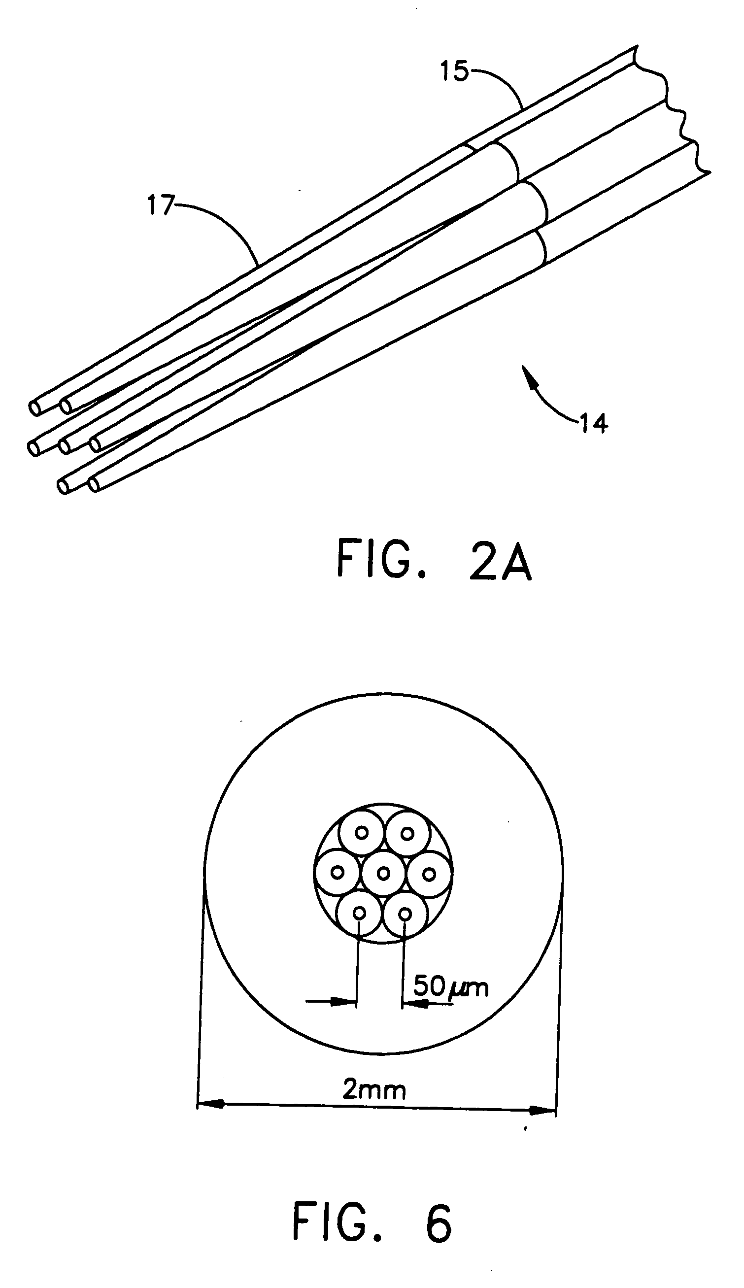
[0017]An improved fiber bundle termination and method of manufacturing is disclosed wherein fiber-to-fiber pitch is minimized by reducing the fiber outside diameter and then packing the fibers with reduced diameter tightly into a fiber bundle termination.
[0018]Reduction of the outer diameter of the fibers may be achieved by etching the cladding of the fibers. Provision is also made to prevent breakage of the etched fibers.
[0019]The fiber bundle termination with reduced fiber-to-fiber pitch may be used with fiber optical switches, fiber couplers, circulators, variable optical attenuators, wavelength selective switches, reconfigurable optical add / drop modules, chromatic dispersion compensators, etc.
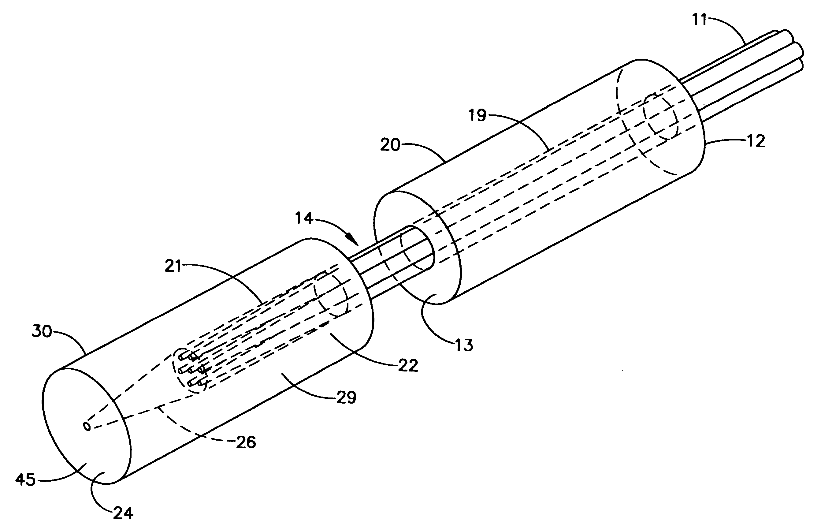
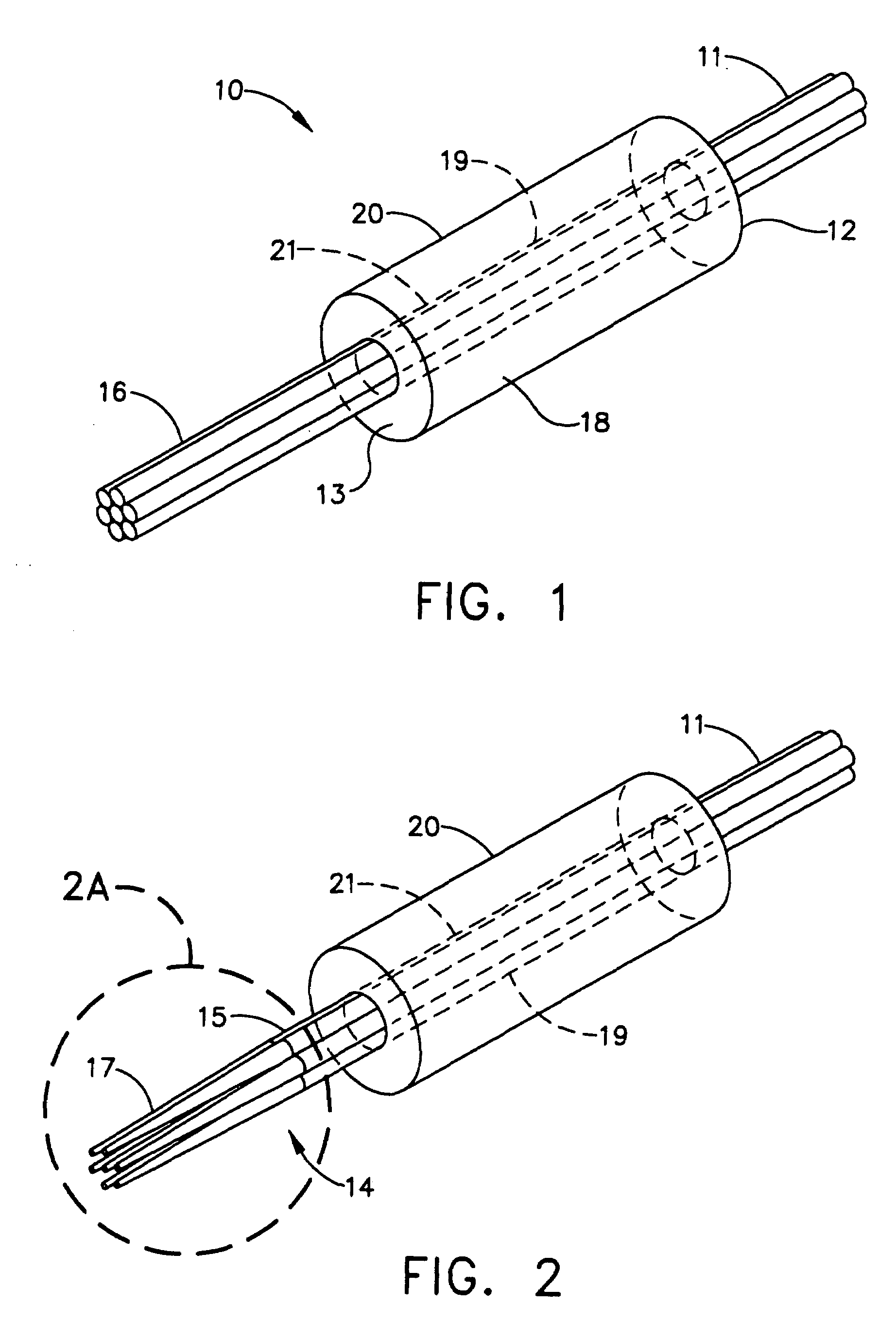
[0020]Referring now to FIG. 1 and steps 52 and 54 of FIG. 5, an improved fiber bundle termination 10 is created by threading a plurality of fibers 11 through a holder 20 having a first endface 12, second endface 13, and inner cavity 19. The fibers 11 are fixedly secured in the holder 20. A ...
PUM
| Property | Measurement | Unit |
|---|---|---|
| Distance | aaaaa | aaaaa |
Abstract
Description
Claims
Application Information