
Fiber bundle termination with reduced fiber-to-fiber pitch

a fiber bundle and fiber-to-fiber technology, applied in glass making apparatus, manufacturing tools, instruments, etc., can solve the problems of difficult handling and extremely fragile fibers with small outside diameter, and achieve the effect of reducing fiber-to-fiber pitch and high yield fabrication and assembly process

Inactive Publication Date: 2008-09-02
THE BOEING CO
View PDF16 Cites 33 Cited by
  • Summary
  • Abstract
  • Description
  • Claims
  • Application Information

AI Technical Summary

Benefits of technology

The patent describes a way to make fiber bundles with smaller gaps between the fibers. This is done by first putting the fibers into a holder to protect them, and then using a chemical process to make the fibers smaller in diameter. The fibers are then assembled into a bundle termination, which secures them tightly and reduces the chance of damage. The process also has a high yield, meaning it can produce many fiber bundles with small gaps between the fibers.

Problems solved by technology

Fibers with small outside diameter are extremely fragile and are very difficult to handle.

Method used


Image

  • Fiber bundle termination with reduced fiber-to-fiber pitch
  • Fiber bundle termination with reduced fiber-to-fiber pitch
  • Fiber bundle termination with reduced fiber-to-fiber pitch

Examples


Embodiment Construction

[0017]An improved fiber bundle termination and method of manufacturing is disclosed wherein fiber-to-fiber pitch is minimized by reducing the fiber outside diameter and then packing the fibers with reduced diameter tightly into a fiber bundle termination.

[0018]Reduction of the outer diameter of the fibers may be achieved by etching the cladding of the fibers. Provision is also made to prevent breakage of the etched fibers.

[0019]The fiber bundle termination with reduced fiber-to-fiber pitch may be used with fiber optical switches, fiber couplers, circulators, variable optical attenuators, wavelength selective switches, reconfigurable optical add / drop modules, chromatic dispersion compensators, etc.

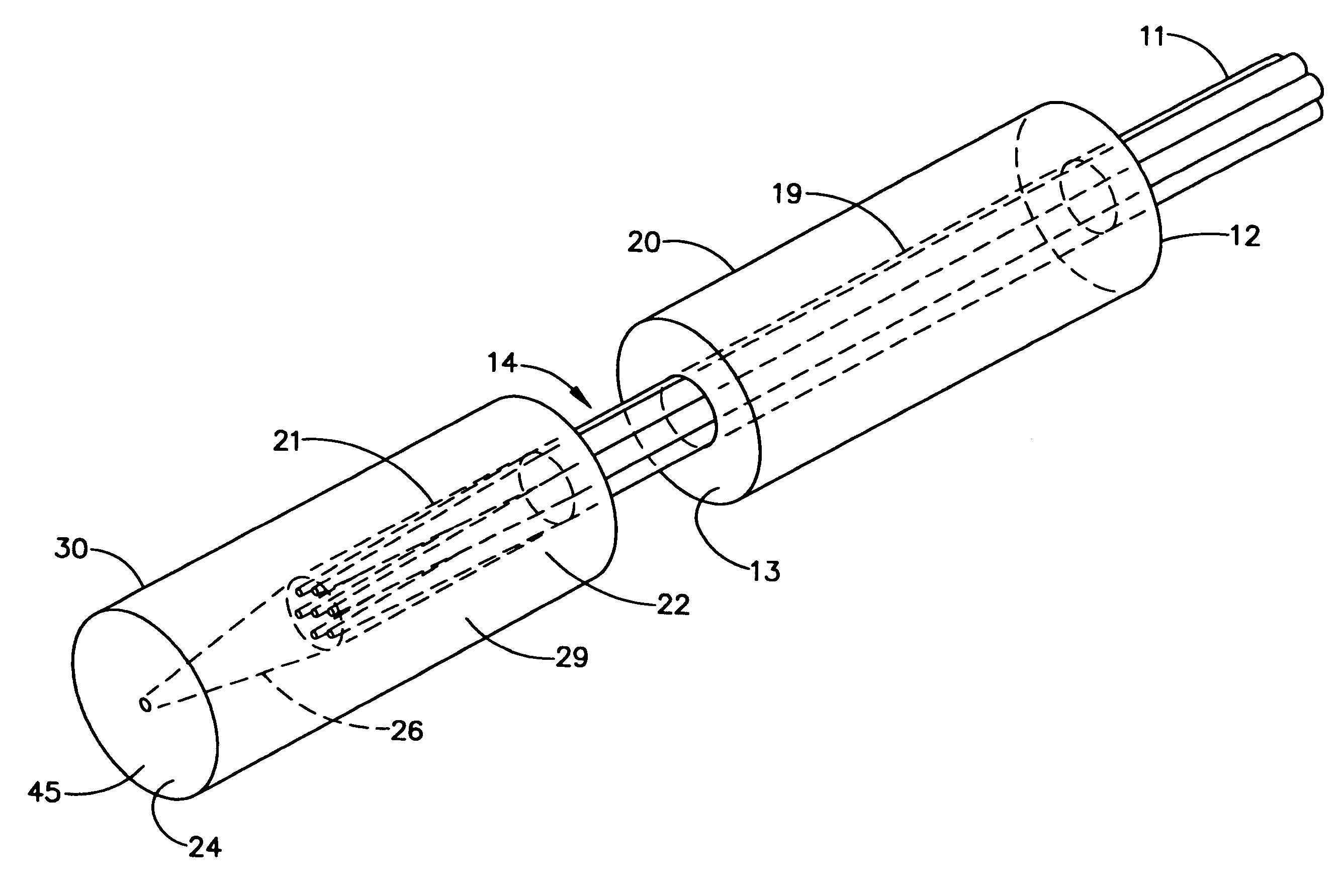
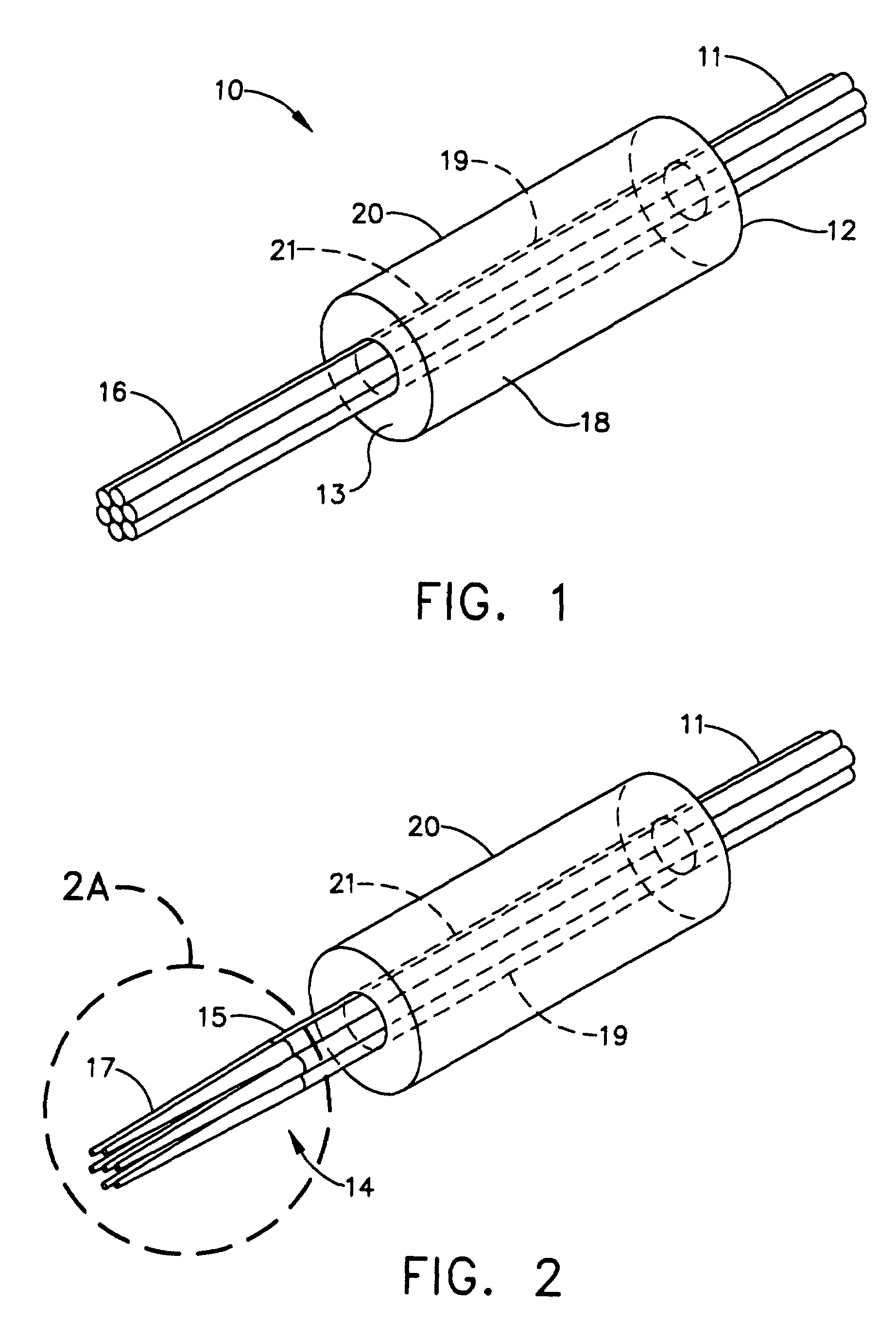
[0020]Referring now to FIG. 1 and steps 52 and 54 of FIG. 5, an improved fiber bundle termination 10 is created by threading a plurality of fibers 11 through a holder 20 having a first endface 12, second endface 13, and inner cavity 19. The fibers 11 are fixedly secured in the holder 20. A ...


PUM

PropertyMeasurementUnit
diameteraaaaaaaaaa
diameteraaaaaaaaaa
outer diameteraaaaaaaaaa

Abstract

A method of fabrication of a fiber bundle termination with reduced fiber-to-fiber pitch which includes reducing the outside diameter of fibers in the fiber bundle by etching and provides means for preventing breakage of the etched fibers during etching and assembly. A high yield fabrication and assembly process is described.

Description

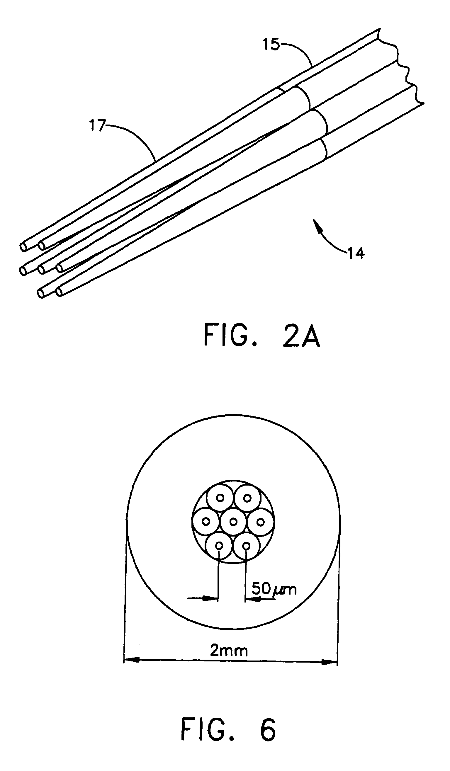
BACKGROUND OF THE INVENTION[0001]Modern information systems require a high speed data transmission. Fiber optical systems provide a high bandwidth and are widely use in communication systems. Fiber optic bundles are commonly utilized in fiber optical systems to increase the communication bandwidth. Many methods of creating fiber bundles exist. They include crimping, tie cables, insertion of fibers into ferrules, etc. Of particular interest are the efforts to reduce fiber-to-fiber pitch because many applications require or benefit from fiber bundles having a small fiber-to-fiber pitch. For example, a liquid crystal beam steering-based 1×6 fiber optical switch, which inherently utilizes a small steering angle, requires fiber bundles with fiber-to-fiber pitch of 50 μm or less to operate. In another example, in MEMS (Micro Electronic Mechanical System) micromirror-based switch, the beam deflection angle is proportional to micromirror's tilt angle. A fiber bundle with smaller fiber-to-fi...

Claims


Application Information

Patent Timeline
Patent Type & Authority Patents(United States)
IPC IPC(8): G02B6/40
CPCG02B6/25G02B6/403G02B6/351G02B6/3861G02B6/3554
Inventor MA
Owner THE BOEING CO
Learn More