Busbar Module

a busbar module and module technology, applied in the field of busbar modules, can solve the problems of increasing the difficulty in increasing the efficiency of work of attaching the busbar module to the battery assembly, and increasing the stiffness of the busbar module, so as to improve increase the ease of attachment, and deform flexibly

Active Publication Date: 2020-12-17
YAZAKI CORP
View PDF0 Cites 6 Cited by
  • Summary
  • Abstract
  • Description
  • Claims
  • Application Information

AI Technical Summary

Benefits of technology

[0028]In general, even in the case where a flexible circuit board includes a number of circuit structures, it can be deformed flexibly by a much weaker force than the electric wires used in the above-described conventional busbar module. Thus, the ease of attachment of the circuit body to the battery assembly is increased remarkably.
[0029]As such, the busbar module having this configuration is higher in the ease of attachment to the battery assembly and the followability to deformation and manufacture dispersion of the battery assembly and is also higher in the degree of freedom of selection of an installation location and a structure of an external device than the above-described conventional busbar module.
[0030]According to second aspect of the invention, relating to the item [2], like each busbar branch strip connected to the associated busbar, the device branch strip to

Problems solved by technology

As a result, when the voltage detection lines are formed by bundling such a large number of electric wires, the stiffness of all the voltage detection lines (and hence the stiffness of the busbar module) is increased, which makes it difficult to increase the efficien

Method used


Image

  • Busbar Module
  • Busbar Module
  • Busbar Module

Examples


embodiment

Main Advantages of Embodiment

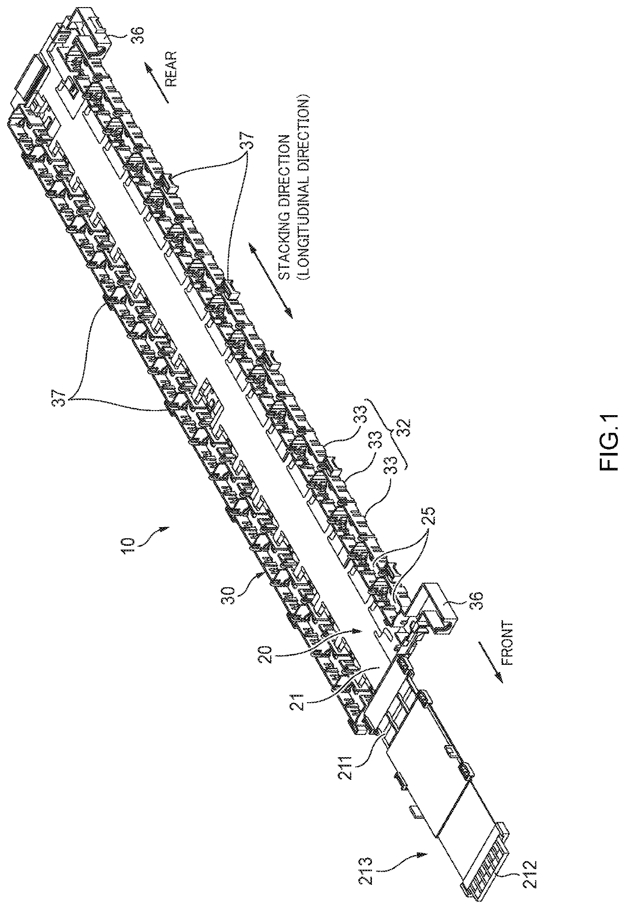
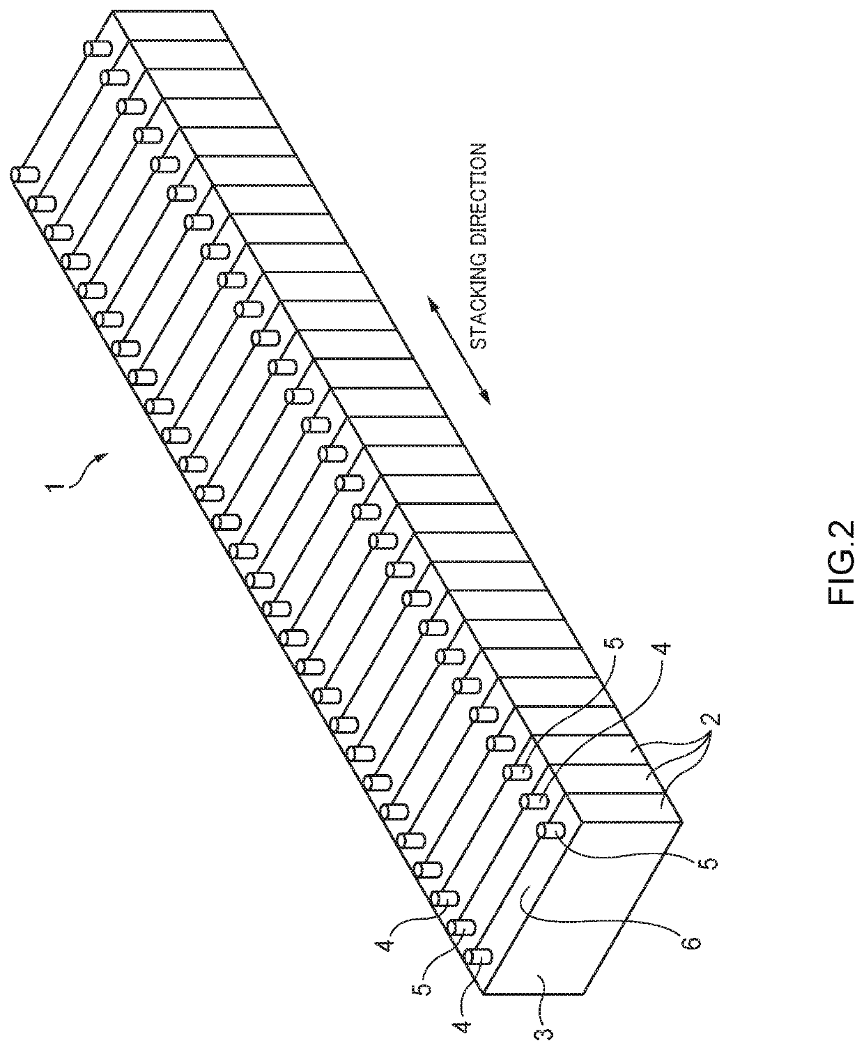
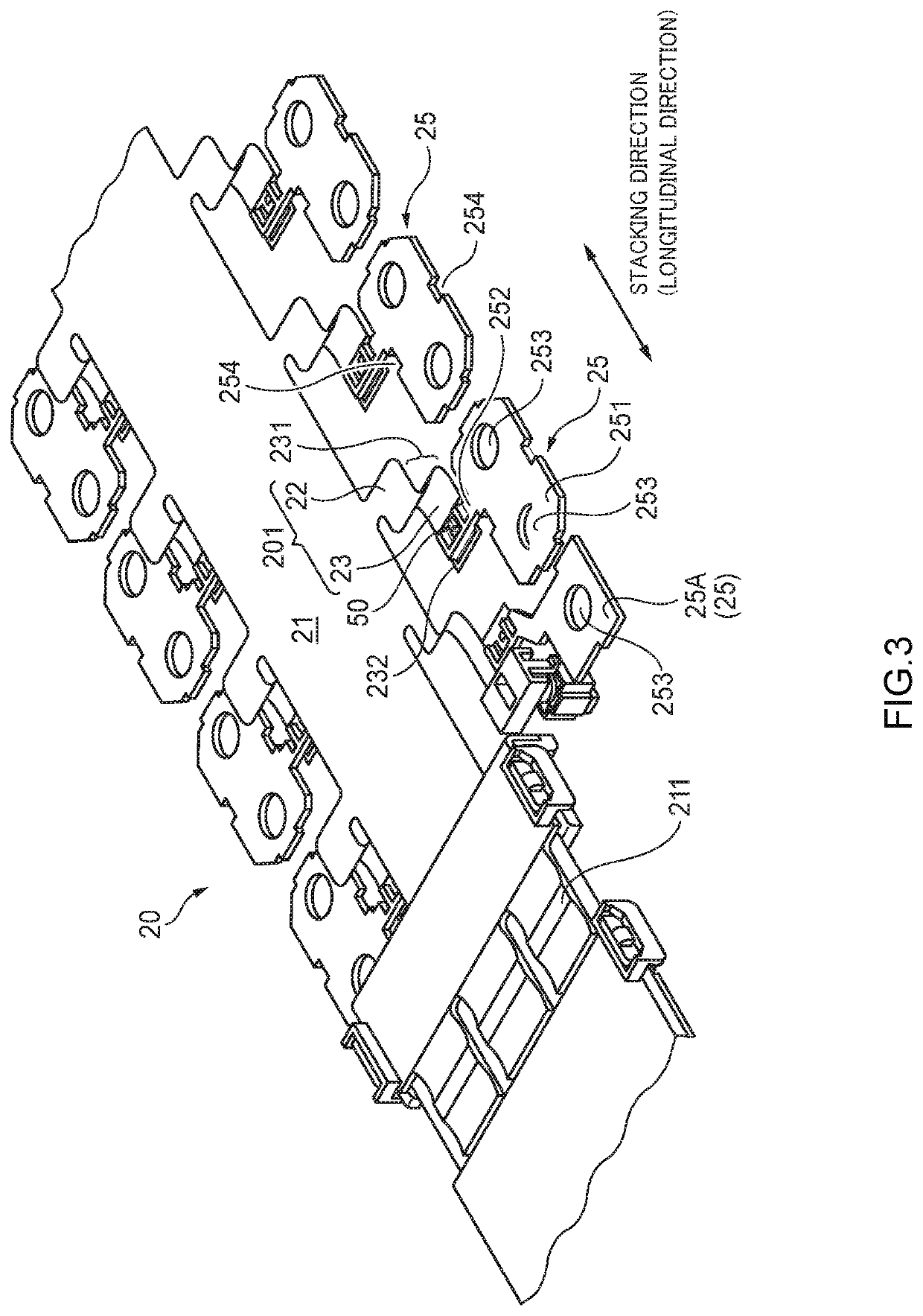
[0078]As described above, in the busbar module 10 according to the embodiment, the circuit body 20 which is a flexible circuit board (FPC) is composed of the band-shaped main strip 21, the band-shaped busbar branch strips 201 which branch off the main strip 21, and the device branch strip 401. Each of the busbar branch strips 201 connected to the respective busbars 25 includes the bent portion 231 which is bent along axes that cross the stacking direction of the plurality of cells 2. With this configuration, when the battery assembly 1 extends or contracts in its stacking direction due to thermal deformation of each cell 2, each busbar 25 can move in the stacking direction of the cells 2 because the bent portion 231 of each busbar branch strip 201 of the circuit body 20 is bent or stretched. Likewise, dispersion of the size of the battery assembly 1 in its stacking direction due to an assembling allowance of each cell 2 can be absorbed by bending or stre...


PUM


Abstract

A busbar module includes: a circuit body having a flexible circuit board; busbars; and a holder. The circuit body has: a band-shaped main strip to be located to extend in a stacking direction of cells; a band-shaped first branch strip branched from the main strip and extending toward a corresponding busbar; and a second branch strip branched from the main strip and extending toward an external device. The first branch strip has: a bent portion extending in the stacking direction and having a bent shape around an axis crossing the stacking direction; and a busbar connection portion disposed closer to an end of the first branch strip than the bent portion and connected to the corresponding busbar. The second branch strip has a device connection portion to be connected to the external device.

Description

CROSS-REFERENCES TO RELATED APPLICATION(S)[0001]This application is based on and claims priority from Japanese Patent Application No. 2019-112232 filed on Jun. 17, 2019, and the entire contents of which are incorporated herein by reference.BACKGROUNDField of the Invention[0002]The present invention relates to a busbar module.Description of Related Art[0003]Conventionally, busbar modules are used in such a manner as to be attached to a battery assembly (i.e., a battery module in which plural battery cells are laid on each other) that is a drive power source installed in an electric vehicle, a hybrid vehicle, or the like.[0004]The busbar module disclosed in Patent document 1 is equipped with plural busbars each of which connects a positive electrode and a negative electrode of adjacent ones of battery cells laid on each other and voltage detection lines that are connected to the respective busbars and serve to monitor the individual battery cells. The voltage detection lines are a bun...

Claims


Application Information

Patent Timeline
IPC IPC(8): H05K1/02H01M2/20H01M50/209H01M50/503H01M50/507H01M50/522
CPCH01M2220/20H05K2201/10272H01M2/206B60R16/033H05K1/0277H05K2201/10189H05K1/189H01M10/425H01M10/4207G01R31/3644H01R11/288H05K1/0265H05K2201/052H05K2201/10037Y02E60/10H01M50/284H01M50/507H01M50/291H01M50/503H01M50/209H01M50/522
Inventor YASUDA, TOMOJIICHIKAWA, YOSHIAKIOGA, TATSUYA
Owner YAZAKI CORP
Why Eureka
Try Eureka