
Ga-base alloy and organic function element using the same

a technology of organic function elements and alloys, applied in the field of metal materials for electrode formation, can solve the problems of high oxidizability and high combustibility, increase in vacuum devices and deposition masks, and difficulty in handling alkali metals and alkaline earth metals, etc., to achieve the effect of reducing production costs, low production costs, and increasing the size of organic function elements

Inactive Publication Date: 2009-12-01
DAI NIPPON PRINTING CO LTD
View PDF6 Cites 2 Cited by
  • Summary
  • Abstract
  • Description
  • Claims
  • Application Information

AI Technical Summary

Benefits of technology

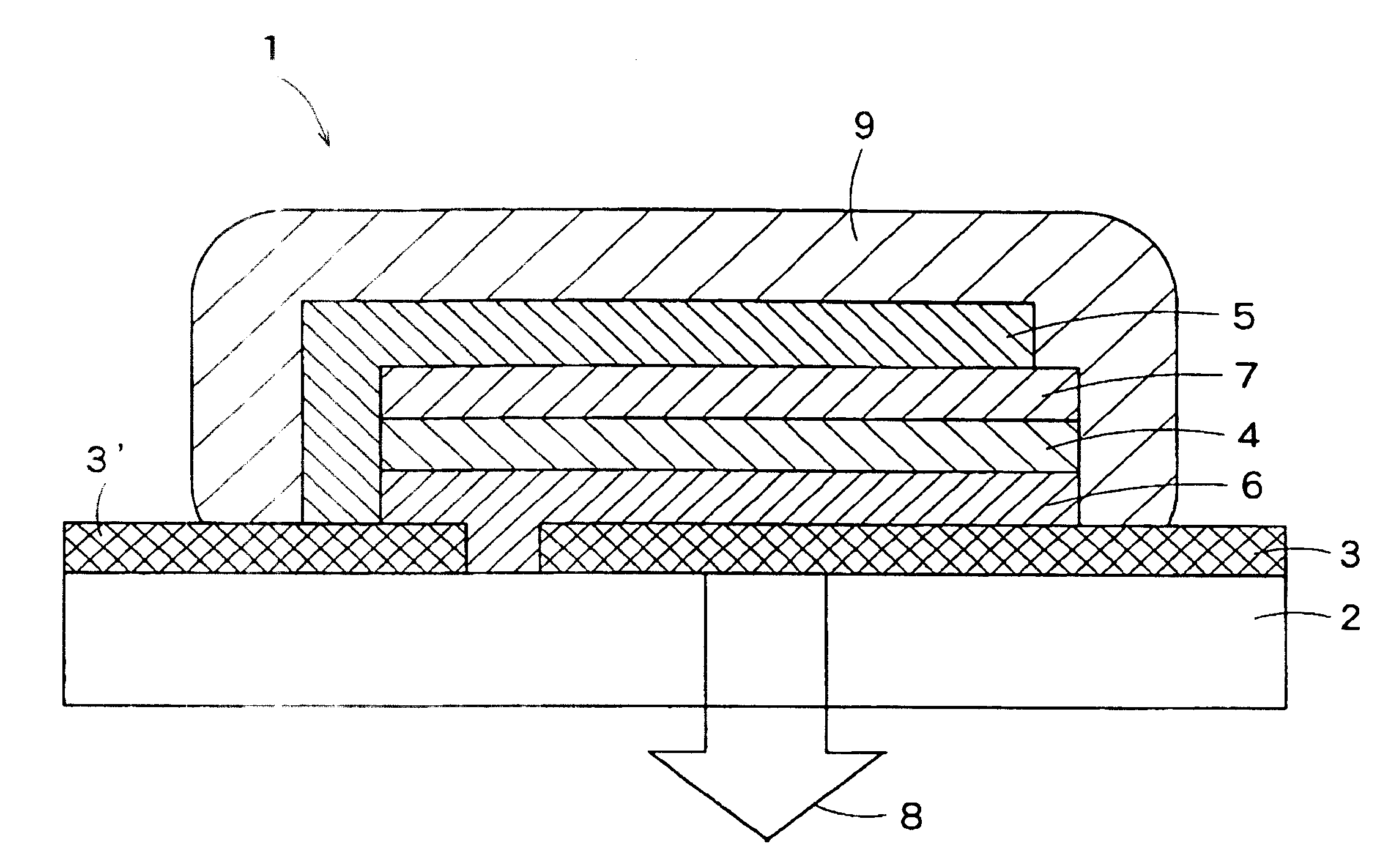
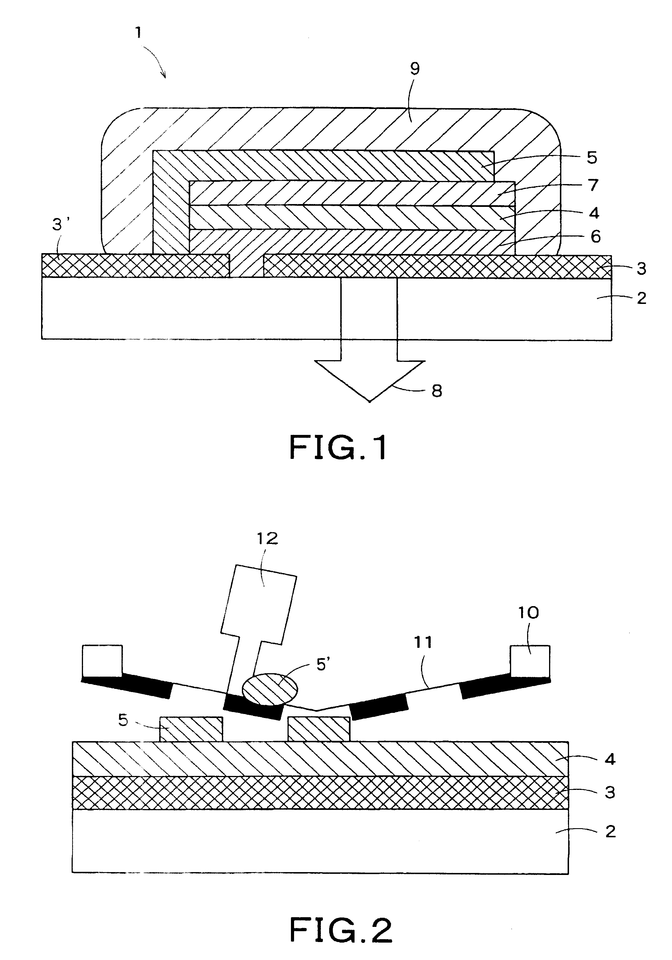
The present invention provides a metal material for electrode formation that can be used in organic function elements without the need for vapor deposition, which is costly and limits the size of the electrode. The metal material is a Ga-base alloy that is in a paste state at room temperature and has electron injection function. The alloy can be easily produced and can form electrodes in various shapes, such as organic semiconductor elements and organic TFT elements. The electrodes formed using the metal material are flexible, reliable, and can conform to flexure without causing disconnection. The use of the metal material in vacuum or inert gas improves the homogeneity of luminescence and percentage completion of the organic function element.

Problems solved by technology

Alkali metals and alkaline earth metals, however, are highly oxidizable and highly combustible in the air and thus are unstable.
Due to these properties, the alkali metals and alkaline earth metals are difficult to handle.
The above problem is found not only in organic EL elements but also in general organic function elements comprising an organic material layer and an electrode.
In mask vacuum deposition for low-molecular materials, an increase in size of a vacuum device and a deposition mask is difficult.
This disadvantageously poses a problem that increasing the size of the substrate is difficult, and the mass production of large elements is difficult.
This means that, although, on a scale of an experimental level in a development stage, the vacuum deposition method can be applied even in the case of a large substrate, in a full-scale mass production stage, market competitiveness is low for tact and cost reasons.
Further, when the step of vacuum deposition is included in the production process, production tact is sometimes delayed due to vacuuming.
Therefore, the feature of organic EL materials which can be coated for film formation cannot be fully utilized.
However, a negative electrode has been an obstacle to the formation of the flexible element.
This publication, however, does not disclose the utilization of the liquid metal as an electrode for energization of an organic material layer or the action of an electric field on the organic material layer for developing the function of organic function elements.
These coating methods, however, are not suitable for thin film formation.
Further, in forming a film by printing a metal paste, there is a fear of causing metal powder to damage the organic EL layer.
Since, however, the organic EL layer is generally an ultrathin film having a thickness of not more then 100 nm, the separation of the organic EL layer is unavoidable.
The separation of the organic EL layer is causative of a fatal trouble of electrical contact between opposed electrodes.
Further, as a matter of course, heat curing of the metal paste poses a problem of disconnection.
As described above, the self-luminous flat display element has excellent features, but on the other hand, it suffers from problems such as difficulties of increasing the size of the substrate, difficulties of mass-producing large elements, and disconnection of electrodes upon flexing.

Method used


Image

  • Ga-base alloy and organic function element using the same
  • Ga-base alloy and organic function element using the same
  • Ga-base alloy and organic function element using the same

Examples


example 1

(1) Preparation of Coating Liquid for Organic EL Layer Formation

[0159]Coating liquids having the following compositions for organic EL layer formation was prepared. In the compositions of the coating liquids, a fluorescent colorant was varied to prepare three coating liquids having different luminescent colors. When the fluorescent colorant is Coumarin 6, green luminescence having a peak at 501 nm is obtained; when the fluorescent colorant is perylene, blue luminescence having a peak at 460 to 470 nm; and when the fluorescent colorant is DCM (dicyanomethylene pyran derivative), red luminescence having a peak at 570 nm is obtained. These were used as luminescent materials for respective colors.

[0160]

Polyvinyl carbazole70parts by massOxadiazole compound30parts by massFluorescent colorant1part by mass(Coumarin 6, perylene or DCM)Monochlorobenzene (solvent)4900parts by mass

(2) Preparation of Metal for Electrode Formation

[0161]An alloy of Ca (calcium) and In (indium) at a molar ratio of ...

example 2

[0175]An element was prepared in the same manner as in Example 1, except that the concentration of Ca in the Ga-base alloy used in Example 1 was changed to 30% by mass. The viscosity of the Ga-base alloy was measured with a rotational viscometer and was found to be 100 Pa·s. However, the viscosity of the Ga-base alloy used in this Example was higher than that of the Ga-base alloy used in Example 1, and, in the screen printing, the Ga-base alloy paste disadvantageously clogged the mesh holes, making it impossible to form a cathode. For this reason, the same electrode pattern as in Example 1 was printed using a stainless steel metal mask. As a result, the cathode could be formed. Subsequently, in the same manner as in Example 1, the electrode of the Ga-base alloy was covered with the adhesive for fixation and sealing to prepare an organic EL element.

[0176]The organic EL element thus prepared was DC-driven using ITO as an anode and the electrode of the Ga-base alloy as a cathode. As a ...

example 3

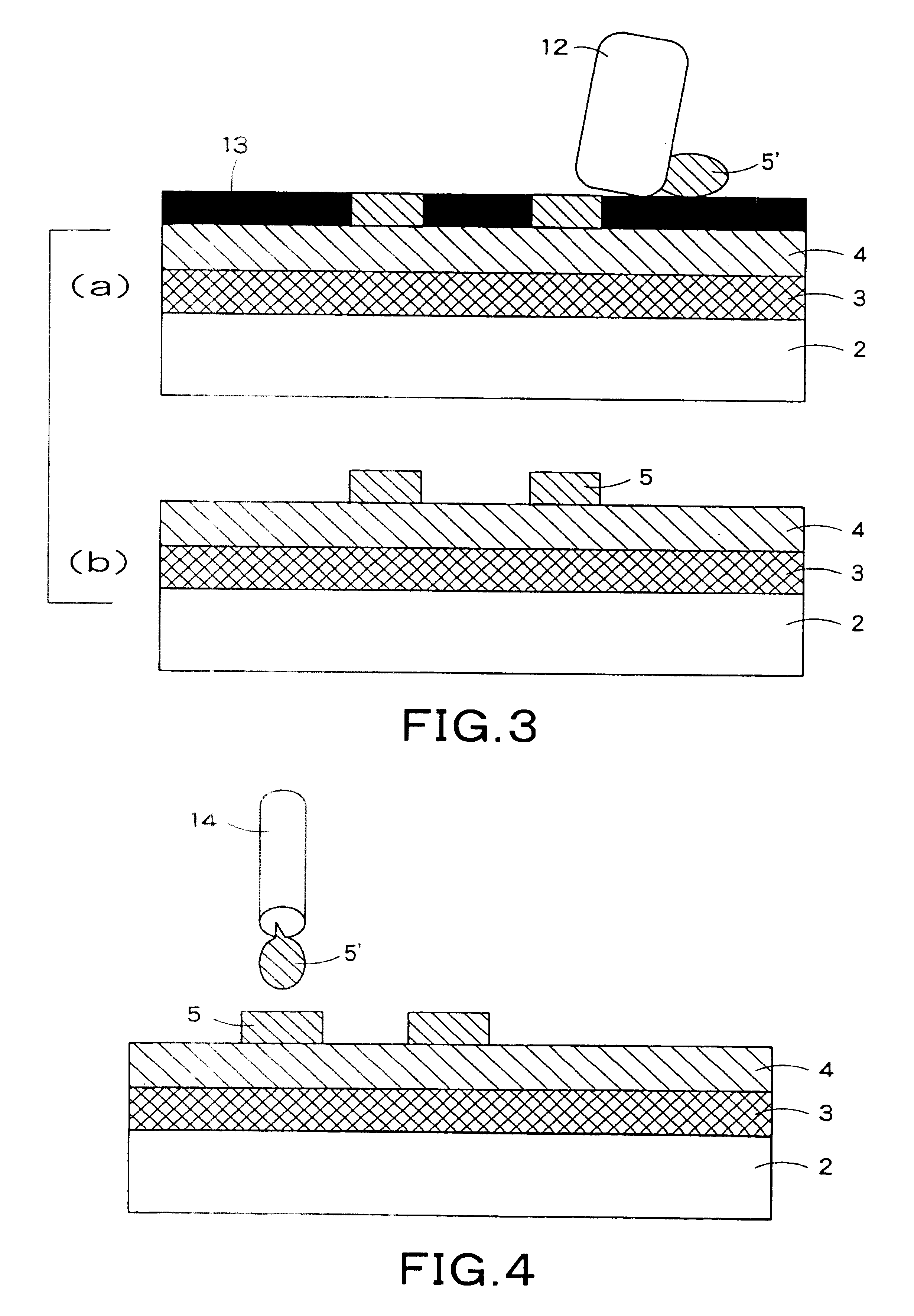
[0178]Elements were prepared in the same manner as in Examples 1 and 2, except that the Ga-base alloy used in Examples 1 and 2 was coated by a dispenser method to form a cathode. In the dispenser method, a metal paste having a wide concentration range can be coated by regulating the nozzle bore diameter, ejection air pressure, and temperature to form a cathode.

[0179]The organic EL elements thus prepared were DC-driven using ITO as an anode and the electrode of the Ga-base alloy as a cathode. As a result, for both the organic EL elements, luminescence started at 2.0 to 2.2 V. At 4.2 to 4.4 V, the luminescence intensity was 100 cd / m2 in terms of luminance, and at 5.8 to 6.0 V, the luminescence intensity was 1000 cd / m2 in terms of luminance. The time necessary for the luminance to be reduced by 50% when the initial luminance was 1000 cd / m2, that is, half-life period, was measured and was found to be 100 hr.

[0180]The above results show that, for the organic EL elements prepared in Examp...


PUM

PropertyMeasurementUnit
temperatureaaaaaaaaaa
melting pointaaaaaaaaaa

Abstract

There are provided a metal material for electrode formation, which can form an electrode provided in an organic function element without adopting vapor deposition, can easily realize an increase in size, can reduce production cost, and does not cause any disconnection of the electrode upon exposure to flexure and, thus, is highly reliable, and, at the same time, has a high level of electron injection function, and an organic function element using the metal material. The metal material is a Ga(gallium)-base alloy which is in a paste state at a temperature of the melting point of the Ga-base alloy or above, the Ga-base alloy comprising at least a Ga-base liquid metal in a liquid state at room temperature and an alkali metal or an alkaline earth metal and having an electron injection function.

Description

BACKGROUND OF THE INVENTION[0001]1. Field of the Invention[0002]The present invention relates to a metal material for electrode formation. More particularly, the present invention relates to a metal material for electrode formation, which can form an electrode without adopting vapor deposition, can easily realize an increase in size, can reduce production cost, and does not cause any disconnection of the electrode upon exposure to flexure and, thus, is highly reliable, and, at the same time, has a high level of electron injection function, and an organic function element using the metal material.[0003]2. Background Art[0004]In organic function elements, for example, organic semiconductor elements, organic thin-film transistor elements (hereinafter referred to as “organic TFT elements”) and organic electroluminescent elements (hereinafter referred to as “organic EL elements”), more charges, particularly electrons, should be injected into an organic material layer.[0005]Substances wit...

Claims


Application Information

Patent Timeline
Patent Type & Authority Patents(United States)
IPC IPC(8): C22C28/00H01L51/52
CPCC22C28/00H01L51/5221H01L2251/5338H10K50/82H10K2102/311H05B33/26
Inventor ITO, NOBUYUKI
Owner DAI NIPPON PRINTING CO LTD
Learn More