Optical System For Converting A Primary Intensity Distribution Into A Predefined Intensity Distribution That Is Dependent On A Solid Angle

a technology of optical system and intensity distribution, applied in the field of optical system, can solve the problems of inability to realize any desired intensity distribution, inability to use array homogenizers, diffractive structures, etc., and achieve the effect of reducing disruptive influence and higher apertures

Inactive Publication Date: 2008-03-27
JENOPTIK LASER OPTIK SYST
View PDF8 Cites 25 Cited by
  • Summary
  • Abstract
  • Description
  • Claims
  • Application Information

AI Technical Summary

Benefits of technology

[0018] Therefore, it is the primary object of the invention while making use of the advantages of diffractive structures in providing variously shaped intensity distributions to reduce the disru

Problems solved by technology

However, a substantial limitation of lens array homogenizers consists in that they cannot be used to realize any desired intensity distributions such as ring-shaped or star-shaped distributions.
A disadvantage of diffractive structures is their susceptibility to manufacturing deviations in the surface profile of the calculated reference profile.
In particular, deviations in the profile depth and duty factor result in an occasionally disruptive increase in intensity due to the zeroth diffraction order which corresponds to the proportion of radiation which passes through the diffractive element without being diffracted and forms a bright punctiform area, or “hot spot”, in the center of a two-dimensionally distributed radiation intensity.
The occurrence of a hot spot of this kind has a progressively disruptive effect as a surface that is to be irradiated homogeneously increases, since the ratio of the light intensity of this hot spot to the light intensity of its homogeneously illuminated surroundings depends on the profile deviation of the diffractive structure on the

Method used


Image

  • Optical System For Converting A Primary Intensity Distribution Into A Predefined Intensity Distribution That Is Dependent On A Solid Angle
  • Optical System For Converting A Primary Intensity Distribution Into A Predefined Intensity Distribution That Is Dependent On A Solid Angle
  • Optical System For Converting A Primary Intensity Distribution Into A Predefined Intensity Distribution That Is Dependent On A Solid Angle

Examples


Embodiment Construction

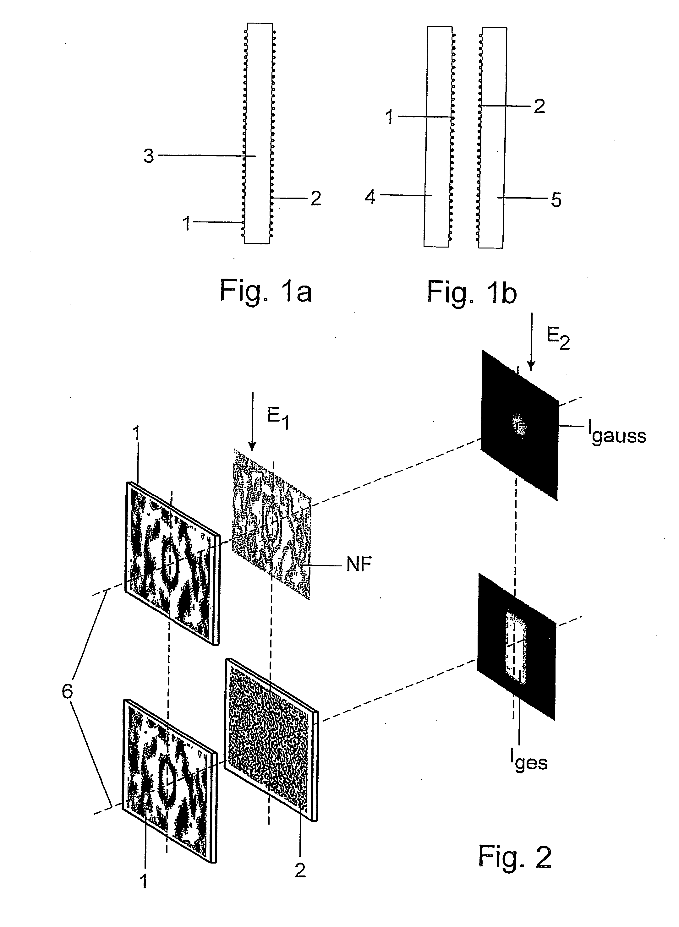
[0043] Homogenizing and / or beam-shaping micro-optic structures, designated for the sake of simplicity as micro-optic homogenization structures 1, 2, are used according to the invention.

[0044] The micro-optic homogenization structures 1, 2 which are arranged in succession can either be arranged on a transparent plate-shaped optical carrier 3 on opposite lateral surfaces (FIG. 1a) or two transparent plate-shaped optical carriers 4, 5 can be arranged adjacent to one another and their surfaces that face one another can have the micro-optic homogenization structures 1, 2 (FIG. 1b).

[0045] The micro-optic homogenization structures 1, 2 can contain diffractive binary structures or diffractive structures with a plurality of height levels or refractive structures with a continuous height profile, e.g., lens array arrangements. Therefore, the surfaces of the transparent optical carriers 3-5 can have diffractive structures or diffractive and refractive structures are combined in that a first ...


PUM


Abstract

It is the object of an optical system and a method for converting a primary intensity distribution into a predetermined intensity distribution dependent on a solid angle to reduce the disruptive influence of the zeroth diffraction order beyond the limits imposed by the manufacturing accuracy in the manufacture of the diffractive structures, also with increasingly higher apertures, while making use of the advantages of diffractive structures in providing variously shaped intensity distributions. In a first plane, in which first micro-optic homogenization structures generate a finely structured amplitude distribution and phase distribution from the primary intensity distribution, there are arranged second diffractive micro-optic homogenization structures which are adapted to the finely structured amplitude distribution and phase distribution and which generate the predetermined solid angle-dependent intensity distribution in a second plane from the finely structured amplitude distribution and phase distribution.

Description

CROSS-REFERENCE TO RELATED APPLICATIONS [0001] This application claims priority of International Application No. PCT / DE2005 / 001268, filed Jul. 15, 2005 and German Application No. 10 2004 035 489.8, filed Jul. 19, 2004, the complete disclosures of which are hereby incorporated by reference.BACKGROUND OF THE INVENTION [0002] a) Field of the Invention [0003] The invention is directed to an optical system for converting a primary intensity distribution into a predetermined intensity distribution which is dependent on a solid angle. The optical system can be used for homogenizing beam shaping for coherent or partially coherent laser sources and for radiation sources emitting in a narrow spectral region. [0004] b) Description of the Related Art [0005] Industrial and scientific use of laser radiation sources has increased enormously in scope and frequency in recent years. Important fields of application include material processing, medical engineering, the semiconductor industry, and measu...

Claims


Application Information

Patent Timeline
IPC IPC(8): G02B27/46
CPCG02B27/0944G02B27/0927
Inventor CUMME, MATTHIAS
Owner JENOPTIK LASER OPTIK SYST
Why Eureka
Try Eureka