Electroluminescent lighting device having high aperture ratio

a technology of electroluminescent lighting and aperture ratio, which is applied in the direction of solid-state devices, semiconductor devices for light sources, lighting and heating apparatus, etc., can solve the problems of degrading the efficiency of the electroluminescent light, and achieve the effect of enhancing the aperture ratio and enhancing the stability of the flexible lighting devi

Active Publication Date: 2021-06-15
LG DISPLAY CO LTD
View PDF2 Cites 0 Cited by
  • Summary
  • Abstract
  • Description
  • Claims
  • Application Information

AI Technical Summary

Benefits of technology

[0005]An electroluminescent lighting device according to the present disclosure protects the light emitting element from external environments (e.g., moisture, oxygen, or the like) and improves the luminescence efficiency / light emitting efficiency and achieves high aperture ratio. The present disclosure also provides a high aperture. electroluminescent lighting device having an enhanced stability and an elongated lifetime.
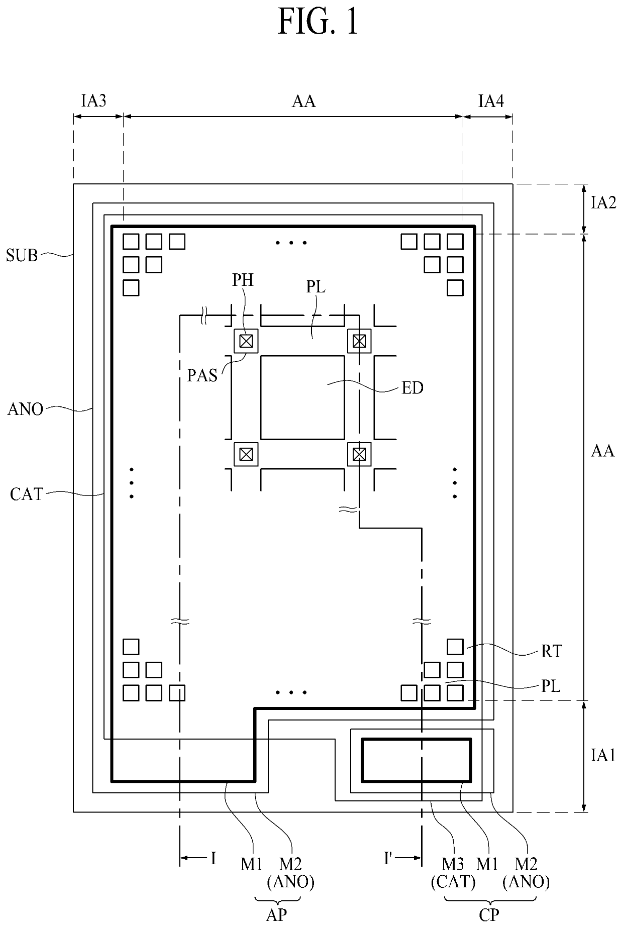
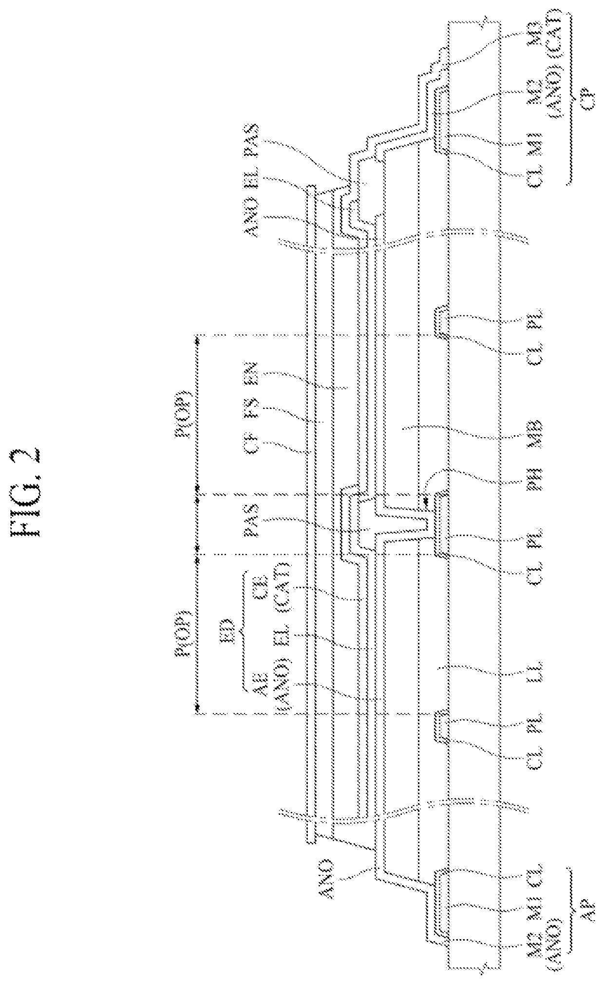
[0016]The electroluminescent lighting device according to the present disclosure has a new structure in which the auxiliary power line is overlapped with the anode electrode not to be directly contacted but to be stacked with an insulation buffer layer there-between. In addition, having a point contact structure in which the anode electrode is connected to the auxiliary power line through a contact hole, the whole area of the anode electrode can be defined as the emission area so that the aperture ratio can be maximized. Further, the short circuit protection structure can be established by the point contact structure between the anode electrode and the auxiliary power line through the contact hole. The short circuit protection can be acquired without specific hardware element, so that the stability of the flexible lighting device could be enhanced.

Problems solved by technology

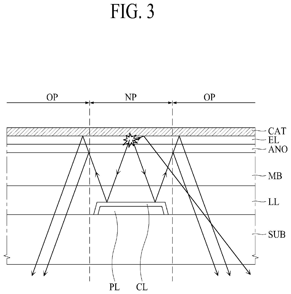
In addition, due to the loss of light amount occurred in the organic light emitting element itself, the luminescent efficiency may be degraded.

Method used


Image

  • Electroluminescent lighting device having high aperture ratio
  • Electroluminescent lighting device having high aperture ratio
  • Electroluminescent lighting device having high aperture ratio

Examples


Embodiment Construction

[0021]Reference will now be made in detail to the exemplary embodiments of the present disclosure, examples of which are illustrated in the accompanying drawings. Wherever possible, the same reference numbers will be used throughout the drawings to refer to the same or like parts. In the specification, it should be noted that like reference numerals already used to denote like elements in other drawings are used for elements wherever possible. In the following description, when a function and a configuration known to those skilled in the art are irrelevant to the essential configuration of the present disclosure, their detailed descriptions will be omitted. The terms described in the specification should be understood as follows. Advantages and features of the present disclosure, and implementation methods thereof will be clarified through following embodiments described with reference to the accompanying drawings. The present disclosure may, however, be embodied in different forms ...


PUM

PropertyMeasurementUnit
thicknessaaaaaaaaaa
areaaaaaaaaaaa
widthaaaaaaaaaa

Abstract

The present disclosure relates to an electroluminescent lighting device having high aperture ratio. The present disclosure provides an electroluminescent light device comprising: a substrate having an emission area and a non-emission area surrounding the emission area; a power line disposed in the emission area and defining an open area; a buffer layer covering the substrate having the power line; a power contact hole formed at the buffer layer for exposing some of the power line; an anode layer disposed on the buffer layer and contacting the power line through the power contact hole; a passivation layer covering the power contact hole on the anode layer; an emission layer on the anode layer; and a cathode layer on the emission layer.

Description

CROSS-REFERENCE TO RELATED APPLICATIONS[0001]This application claims the benefit of the Korean Patent Application No. 10-2018-0173306 filed on Dec. 31, 2018, which is hereby incorporated by reference as if fully set forth herein.BACKGROUNDTechnical Field[0002]The present disclosure relates to an electroluminescent lighting device having a certain light emitting efficiency and aperture ratio.Description of the Related Art[0003]Recently, a series of researches has been actively conducted to use an organic light emitting element as a light source of the lighting device or a display device, based on many advantages and / or merits of an organic light emitting device. For example, a surface light source and / or a point light source applied with the organic light emitting element are applied to the lighting system for the vehicles such as an interior mood lamp, a head lamp, a fog lamp, a retracted lamp, a car light, a number light, a tail lamp, a brake light, a turn signal lamp and so on.[00...

Claims


Application Information

Patent Timeline
Patent Type & Authority Patents(United States)
IPC IPC(8): H01L51/10H01L51/50H01L51/52
CPCH01L51/107H01L51/5044H01L51/5064H01L51/5068H01L51/5246H01L51/5262H10K59/123H10K59/124H10K59/122H10K59/131H10K50/813H10K50/805H10K50/814H10K50/82H10K50/8423H10K50/854H10K2102/341F21Y2115/15H10K50/85H10K10/88H10K50/131H10K50/156H10K50/157H10K50/8426
Inventor LEE, KYU-HWANGKIM, CHULHOSONG, TAEJOONLEE, KYUNGHAKIM, TAEOK
Owner LG DISPLAY CO LTD
Why Eureka
Try Eureka