
LED lamp module with adjustable illuminating angle

a technology of led lamps and modules, applied in the field of lamps, can solve the problems of uneven affecting the uniformity of brightness in the illuminating range, and limited heat dispersing ability of heat pipes

Inactive Publication Date: 2008-04-17
LEADER KEY +1
View PDF3 Cites 51 Cited by
  • Summary
  • Abstract
  • Description
  • Claims
  • Application Information

AI Technical Summary

Problems solved by technology

However, the conventional lamp module has following disadvantages.
Firstly, the height of the lamp posts are different when the street lamp being employed in different illuminating situations, the LEDs of the lamp module may only illuminate single direction for the reason of limited emitting angle, then the brightness in the illuminating range are uneven when the lamp module engaged with lamp posts in different height.
Secondly, the lamp module may maintain different angles relative to the ground, which may also impact the uniformity of the brightness in the illuminating range.
Thirdly, the lamp module use the heat pipe for dispersing heat, which has limited attached area between the heat pipe and the LED module, then the ability of heat dispersing of the heat pipe is limited.

Method used


Image

  • LED lamp module with adjustable illuminating angle
  • LED lamp module with adjustable illuminating angle
  • LED lamp module with adjustable illuminating angle

Examples


Embodiment Construction

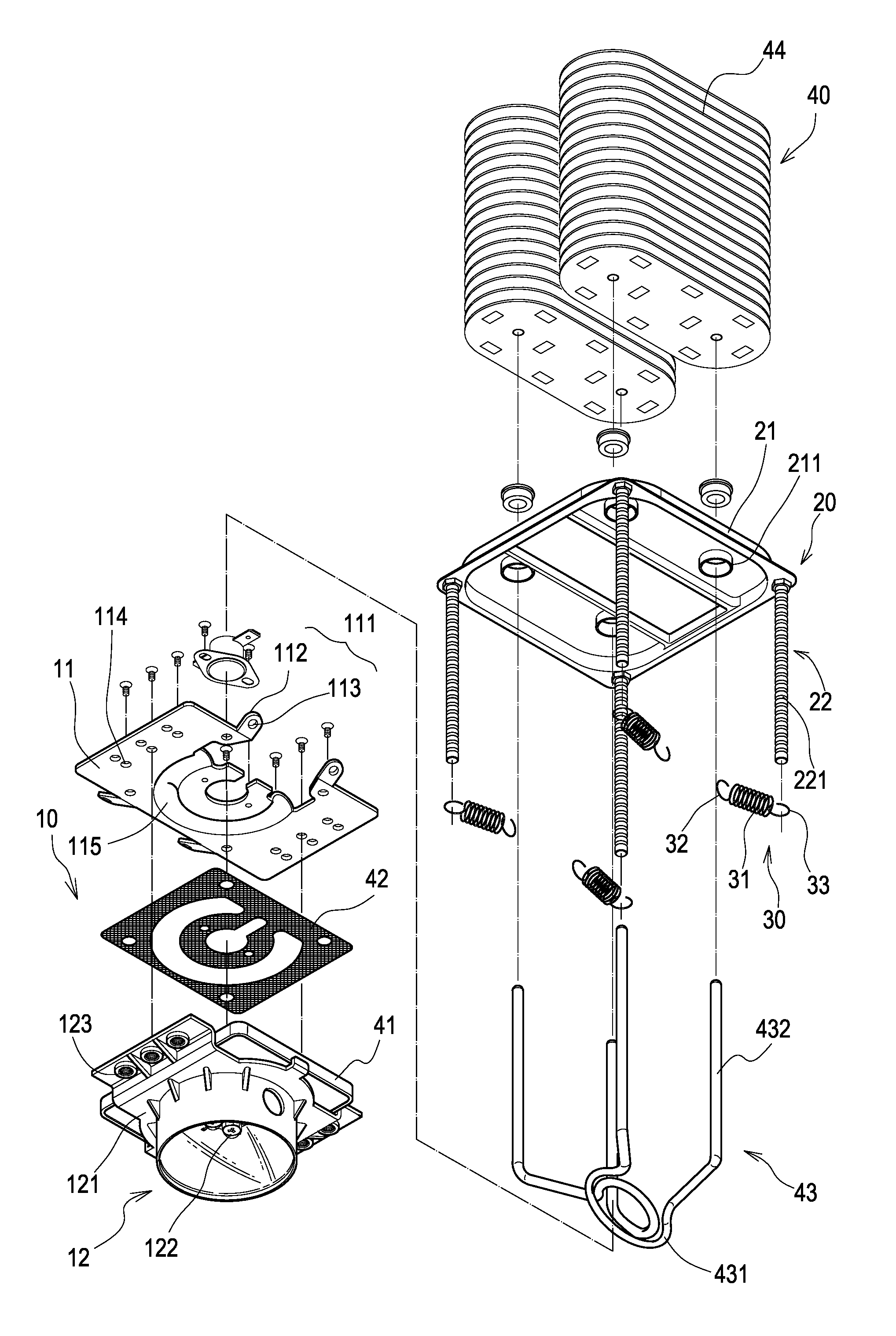
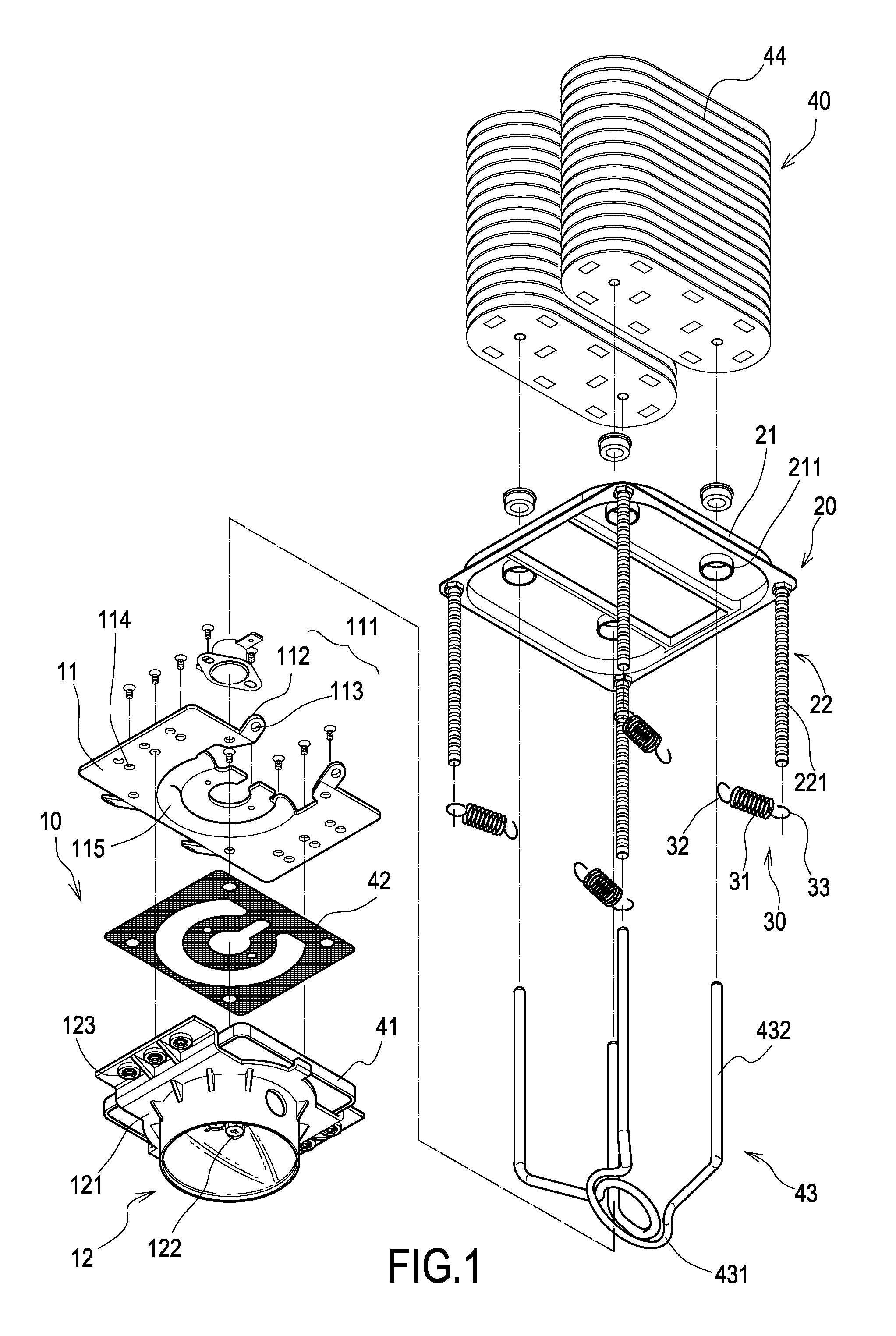
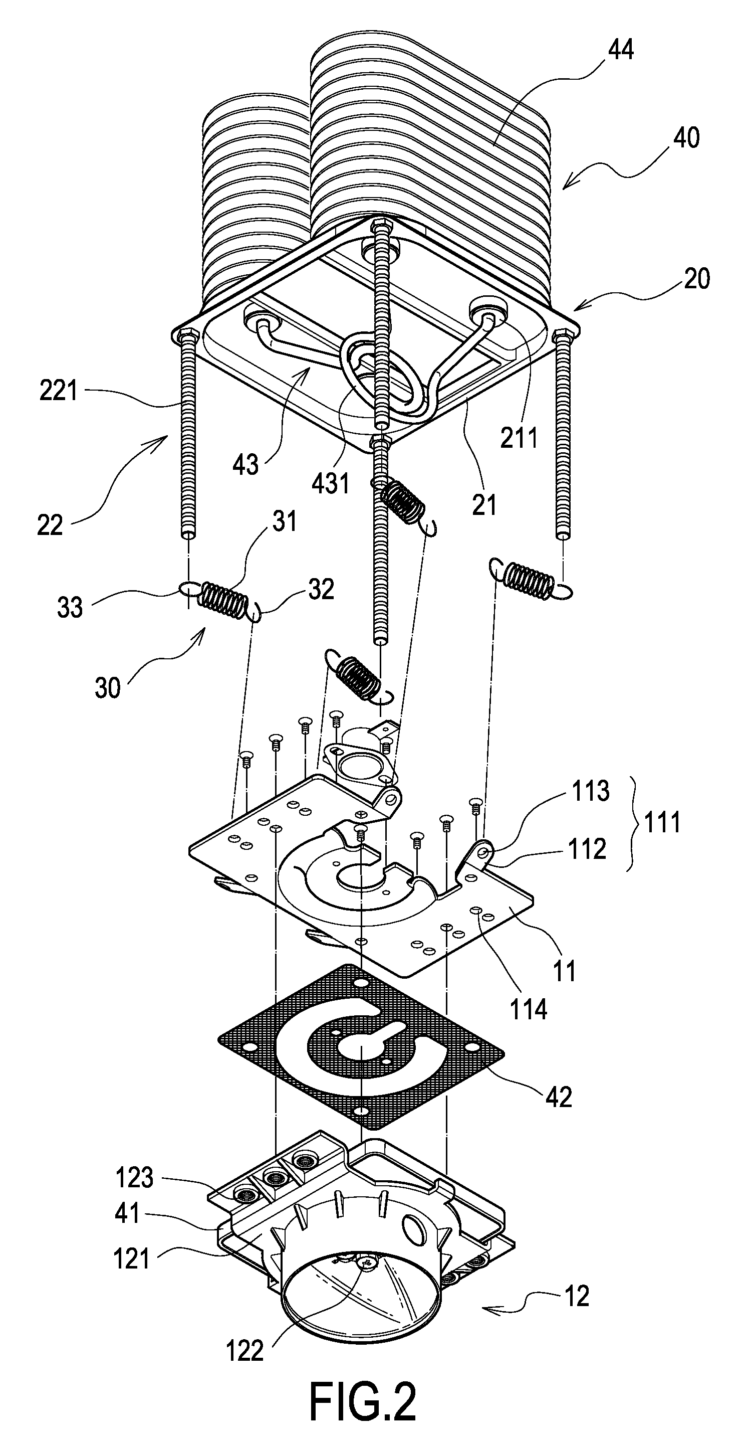
[0015]Referring to FIGS. 1 to 4, FIG. 1 is a perspective, exploded view of an LED lamp module according to an exemplary embodiment of the present invention, FIG. 2 is a perspective, partly assembly view of the LED lamp module of FIG. 1, FIG. 3 is a perspective, assembly view of the LED lamp module of FIG. 1, and FIG. 4 is a cross-sectional view of the LED lamp module of FIG. 1. The LED lamp module includes an LED lamp 10, a fixed base 20, and a plurality of elastic members 30.

[0016]The LED lamp 10 includes a rectangle plate-shaped base 11 and an LED module 12. The base 11 includes a plurality of connecting portions 111 disposed at front and rear portions thereof, which may be ear portions 112 and holes 113 as shown in FIG. 1. The base 11 further includes a plurality of through holes 114 disposed at left and right portions thereof, and an arc-shaped groove 115 disposed at a middle portion of a bottom surface thereof. The LED module 12 includes a cover 121, a plurality of LEDs 122 dis...


PUM


Abstract

An exemplary LED lamp module includes an LED lamp, a fixed base, and a plurality of elastic member. The LED lamp includes a base and an LED module. The base includes a plurality of connecting portions, and the fixed base includes a plate and a plurality of fixed poles corresponding to the connecting portions so as to form a space therebetween for accommodating the LED lamp. Each of the fixed poles includes a plurality of locating grooves. One end of each of the elastic member is connected to the connecting portions of the base, and the other end of each of the elastic member is adjustably fixed to the locating grooves of the fixed poles. The illuminating angle of the LED module may be conveniently adjusted according to different height of the lamp post and the different of the angles between the LED lamp modules relative to the ground.

Description

BACKGROUND[0001]The present invention relates to lamps, and more particularly to a light emitting diode (LED) lamp module, the illuminating angle of the LED lamp module is adjustable.[0002]Because of the advantages of high brightness, lower power consumed and long used life, LEDs are widely used in all kinds of illuminative lamps. Generally, the LEDs are aligned on a circuit board to form an LED module, and the LEDs of the LED module are serially or parallel connected to form the LED lamp having great illuminative range. The LED lamp may be employed in the street lamps.[0003]Laid open Taiwan Patent No. M292042 disclosed a street lamp having a lamp module and a lamp post supporting the lamp module. The lamp module includes a top cover, a light-penetrating mirror disposed under and connected to the top cover, a dividing plate disposed between the top cover and the light-penetrating mirror that is connected to the top cover, an LED module fixed to the bottom surface of the dividing pla...

Claims


Application Information

Patent Timeline
Patent Type & Authority Applications(United States)
IPC IPC(8): F21V29/00
CPCF21S8/086F21V15/04F21Y2101/02F21V29/006F21W2131/103F21Y2115/10F28D15/0275F21S2/005F21V17/12F21V17/104
Inventor WANG, CHIN-WEN
Owner LEADER KEY
Learn More