Process and compound for producing printed design creating three-dimensional visual effect

a three-dimensional, visual effect technology, applied in the direction of rotary lithographic machines, wet duplicators, magnetic bodies, etc., can solve the problems of inability to meet the requirements of showing novel appearances, high cost of computerized printing equipment, and large increase in printing costs

Inactive Publication Date: 2008-05-01
SANRITZ CORP
View PDF5 Cites 4 Cited by
  • Summary
  • Abstract
  • Description
  • Claims
  • Application Information

AI Technical Summary

Benefits of technology

[0003]A primary object of the present invention is to provide a process and a compound for producing a printed design creating 3D visual effect through an interaction between magnetic particles and a magnetic body.

Problems solved by technology

All these printing techniques use mono or multiple colors to print and create only a two-dimensional flat visual effect, and therefore fail to meet the nowadays requirements for showing novel appearances by effectively upgrading a product's visual impression or creating a 3D visual effect.
However, the computerized printing equipment is expensive to largely increase the cost of printing, while the simulated 3D effect is limited.

Method used


Image

  • Process and compound for producing printed design creating three-dimensional visual effect
  • Process and compound for producing printed design creating three-dimensional visual effect
  • Process and compound for producing printed design creating three-dimensional visual effect

Examples


Embodiment Construction

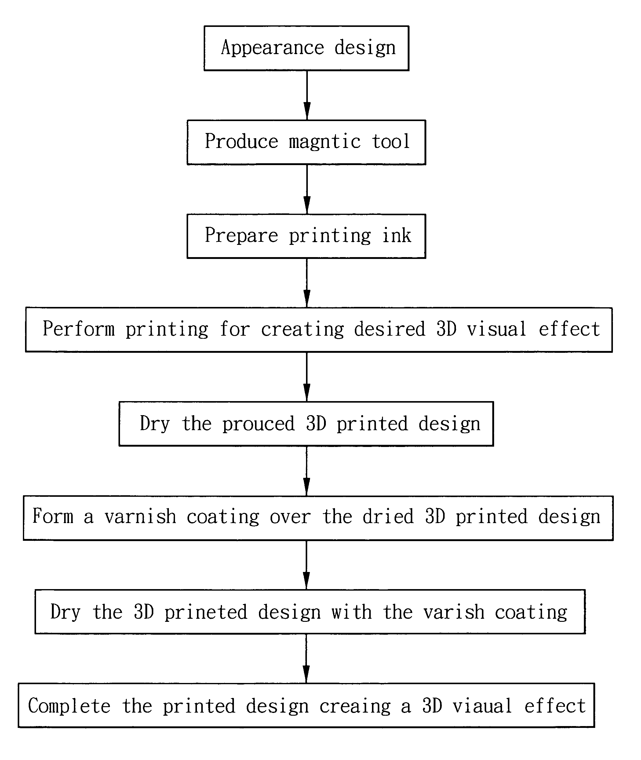
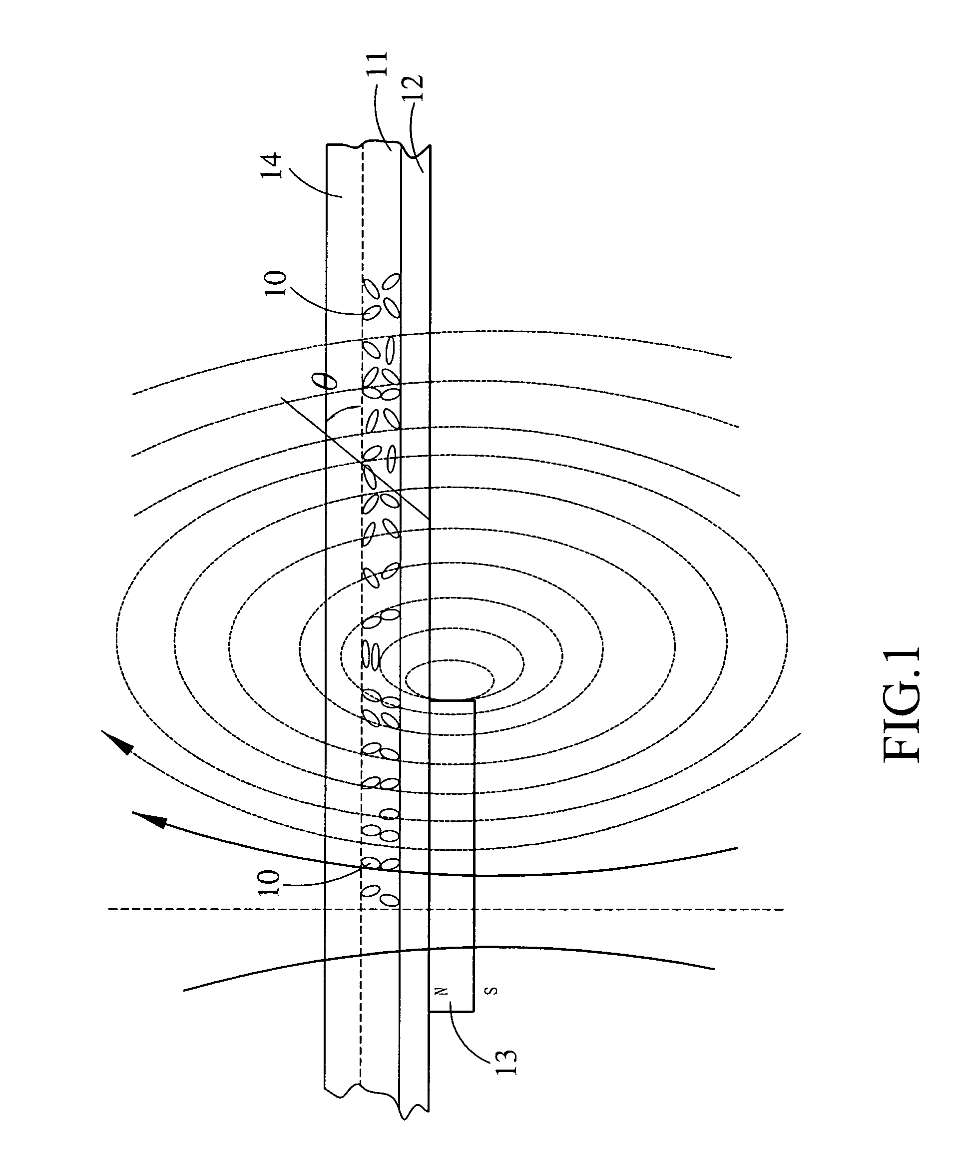
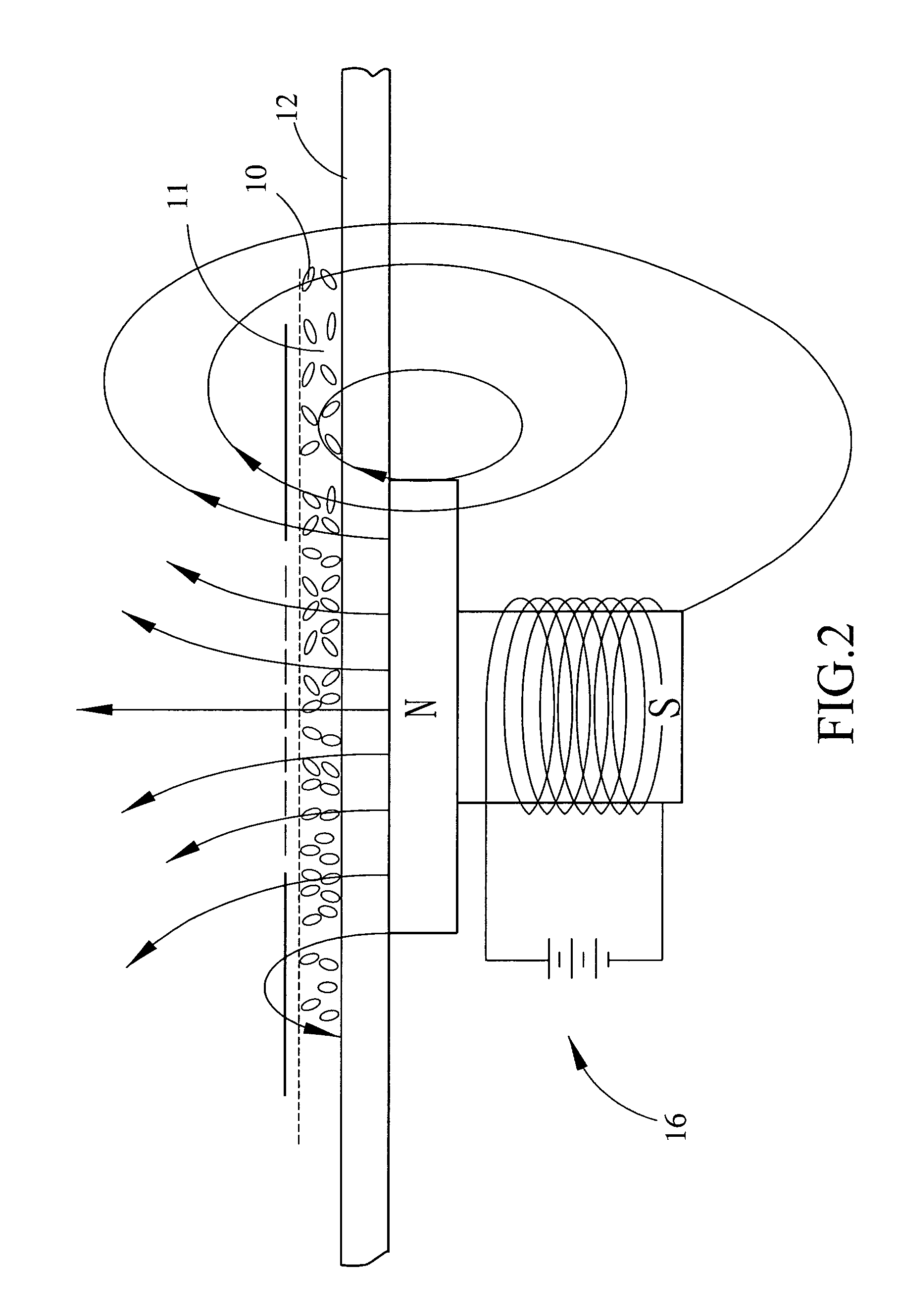
[0013]Please refer to FIG. 1 that shows the mutual relation between magnetic particles in a printing ink of the present invention and a magnetic body. As shown, when a printing ink 11 blended with magnetic particles 10 is applied onto a printing plate 12, and a magnetic body 13 is positioned beneath an area of the applied printing ink 11, at where a three-dimensional (3D) surface is to be created, the magnetic particles 10 in the still wet printing ink 11 are attracted by the magnetic body 13 to gather in the area and create ups and downs therein to show a 3D visual effect.

[0014]The printing process creating 3D visual effect according to the present invention is different from the conventional printing techniques in that the present invention may be implemented with an existing printing apparatus 15 (see FIGS. 3, 4, and 5) without the need of designing a new one. On the printing apparatus 15, a compound disclosed in the present invention, which is a type of printing ink, for produci...


PUM

PropertyMeasurementUnit
wt %aaaaaaaaaa
wt %aaaaaaaaaa
wt %aaaaaaaaaa

Abstract

In a process for producing a printed design creating 3D visual effect, a compound consisting of a printing ink blended with magnetic particles is used. The printing ink containing the magnetic particles is applied onto a printing plate on a printing apparatus, and a tool capable of producing a required magnetic force is positioned at a predetermined area of the applied printing ink, so that the magnetic particles in the printing ink are attracted and gathered to form ups and downs in the area and create a 3D visual effect.

Description

FIELD OF THE INVENTION[0001]The present invention relates to a printed design creating three-dimensional (3D) visual effect, and more particularly to a process and compound for producing a printed design creating 3D visual effect through an interaction between magnetic particles and a magnetic body.BACKGROUND OF THE INVENTION[0002]Conventional printing techniques include silk screen printing, automatic plane screen printing, pad printing, etc. All these printing techniques use mono or multiple colors to print and create only a two-dimensional flat visual effect, and therefore fail to meet the nowadays requirements for showing novel appearances by effectively upgrading a product's visual impression or creating a 3D visual effect. With the wide application of computerized equipment, the color separation in printing process is now carried out using a computer, and a gray scale is employed in printing to present a 3D effect. However, the computerized printing equipment is expensive to l...

Claims


Application Information

Patent Timeline
Patent Type & Authority Applications(United States)
IPC IPC(8): B41M1/00C09D11/02
CPCB41M1/00B41M1/22B41M3/00H01F41/16H01F1/0027H01F13/00C09D11/03
Inventor TAI, HO-CHENG
Owner SANRITZ CORP
Why Eureka
Try Eureka